Challenges in Carbon Fiber Processing: How PCD Tools Can Double the Production Efficiency of CFRP
In workshops dedicated to drilling holes in aerospace fuselage skins, creating slots in carbon fiber battery housings for new energy vehicles, and manufacturing ultra-thin carbon fiber enclosures for 3C electronics, you've likely witnessed this scenario: a newly replaced cemented carbide drill bit shows significant wear after drilling just 30 holes, with persistent high delamination rates—15% of defects alone can render an entire carbon fiber plate worth thousands of yuan completely unusable; during high-speed milling, edge burr heights exceed 0.1 mm, making subsequent manual grinding often take longer than the machining process itself; accumulated cutting heat causes resin carbonization, leaving unsightly black spots on workpieces that result in immediate rejection as defective products.
These challenges that plague countless manufacturers are precisely the true picture of carbon fiber reinforced plastic (CFRP) processing. As a high-end material combining lightweight and high-strength properties, CFRP's application has grown steadily over the years; however, its unique "strong yet brittle" nature poses significant obstacles to conventional processing methods. The advent of PCD (polycrystalline diamond) tools is now emerging as the ultimate solution to these processing difficulties.
1. Addressing the four major pain points in CFRP processing – how many of these apply to you?
Carbon fiber composites are heterogeneous materials composed of carbon fiber reinforcements and a resin matrix laminated together. The physical properties of these two components differ significantly, and their fracture mechanisms during machining are entirely distinct from those of traditional metals. Processing challenges persist throughout the entire manufacturing process.
1. Interlayer delamination and fiber tearing result in an almost zero tolerance for defects. The bonding strength between CFRP layers is extremely weak, making axial forces during drilling highly susceptible to interlayer separation—a defect commonly referred to as the "thousand-layer cake defect" in the industry. The aviation sector explicitly requires that the delamination area around holes must not exceed 15%; exceeding this limit leads to immediate scrapping of the entire skin. This exceptionally low tolerance for defects has kept yield rates in many workshops consistently around 80%, resulting in persistently high material waste costs.
2. The high abrasiveness causes tools to fail rapidly, and frequent tool changes significantly reduce production capacity. Carbon fiber has a hardness of HRC 50–60, comparable to that of high-speed steel. With traditional cemented carbide tools, wear on the back face reaches 0.2 mm before failure occurs, limiting their service life to just 30–50 holes. The time required for frequent tool changes and adjustments substantially lowers the utilization rate of automated production lines, making it impossible to achieve the originally planned production targets.
3. Anisotropy leads to the formation of numerous burrs and significantly increases post-processing costs. The directional nature of carbon fiber fibers results in highly uneven distribution of cutting forces, with substantial variations in cutting resistance across different layering angles, making processed edges prone to generating extensive sharp burrs. If residual burrs remain in weight-reduction holes within new energy vehicle battery casings, they may even penetrate the insulation layer and pose short-circuit risks. Consequently, many manufacturers must employ extensive manual re-polishing efforts, with post-processing time often exceeding that required for machining alone.
4. Cutting heat induces resin carbonization, leading to loss of precision stability. Carbon fibers exhibit extremely poor thermal conductivity; during dry-cutting, heat cannot dissipate rapidly, causing rapid temperature spikes in the cutting zone that result in resin matrix softening, tool adhesion, and carbonization with blackening. Additionally, due to the material's high linear expansion coefficient, elastic recovery after processing often leads to shrinkage cavities, making it difficult to maintain consistent tolerance control for cavity size. This results in significant dimensional accuracy variations during mass production and challenges in controlling defect rates.
II. PCD Tools: Customized Solutions Addressing Key Challenges in CFRP Applications
To address these common challenges across industries, PCD tools have achieved precise solutions to the key difficulties in CFRP processing through dual innovations in materials and structure.
The PCD cutting edge employs a nanoscale manufacturing process, achieving a surface roughness of Ra 0.05 μm. Paired with an ultra-high-hardness diamond insert (HV6000) and a high-strength hard alloy matrix, it delivers exceptional sharpness while maintaining robust impact resistance, fundamentally addressing the performance limitations of conventional cutting tools.
l Wear resistance improved by more than 10-fold: The diamond cutting edge withstands high abrasion from carbon fibers, with a service life far exceeding that of hard alloy tools. It remains sharp even after processing thousands of holes consecutively, significantly reducing tool change frequency and enabling uninterrupted operation on automated production lines.
l The burr formation rate is reduced by 90%: The sharp nanoscale cutting edge directly cuts carbon fiber fibers instead of using the conventional "shearing" mode, significantly lowering cutting force and eliminating delamination and tearing defects at their source. Post-processing burr height can be controlled below 0.02 mm, requiring virtually no secondary grinding.
l Resin carbonization risk reduced by 70%: The optimized spiral groove chip discharge design ensures rapid removal of cutting heat along with chips, preventing heat accumulation in the machining zone and effectively addressing resin tool adhesion and surface carbonization issues, thereby ensuring both workpiece appearance quality and internal strength.
l Precision stability has been significantly enhanced: The long-term stable cutting edge condition enables consistent control of hole diameter tolerances within ±0.02 mm during mass production, fully meeting the stringent precision assembly requirements of high-end sectors such as aerospace and new energy vehicles.
III. Real-world testing across three premium use cases demonstrates dual improvements in efficiency and quality
PCD tools have now been widely deployed across multiple high-end manufacturing sectors, with their practical performance extensively validated by leading industry players.
In aerospace aircraft structural component manufacturing, the Airbus A350 fuselage frame requires drilling tens of thousands of rivet holes. The PCD sandwich drill can continuously process thousands of holes without significant wear, maintaining stable hole diameter tolerances that meet aviation-grade precision requirements while achieving over 40% improvement in overall machining efficiency.
In the manufacturing of carbon fiber battery enclosures for new energy vehicles, PCD tools enable burr-free slotting and weight-reducing hole processing, reducing unit processing time by 40%. This solution completely eliminates the safety risk of burrs penetrating the insulation layer, while improving the yield rate from 82% to 98%.
In the micropore machining of ultra-thin carbon fiber casings for 3C electronics, the high-rigidity PCD cutting edge prevents edge chipping at hole openings, significantly improving the yield rate of micropore processing and meeting the industry's stringent demands for extreme thinness in consumer electronics.
IV. In Conclusion
The processing challenges of carbon fiber composites fundamentally stem from the mismatch between traditional tool performance and the unique properties of these materials. With growing adoption of carbon fiber in aerospace lightweight components and new energy vehicles, PCD tools have become essential standards in CFRP processing. They address not merely tool wear issues but also overcome the critical barrier to large-scale, efficient, and precision processing of CFRP materials at their core.
If you're still struggling with issues like layering, burrs, and rapid tool wear in carbon fiber machining, consider our customized PCD tool processing solution. By employing a tooling process tailored to the material's properties, you can eliminate the inefficient production cycle of repeated cutting trials and frequent tool changes.
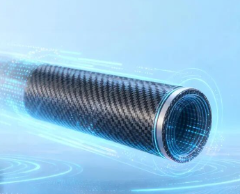
Processing of carbon fiber composite bushings
Xinrui Zhi (Shenzhen) Precision Machinery Co., Ltd., a leading manufacturer of superhard cutting tools, offers reliable machining tool solutions specifically designed for processing carbon fiber composite materials using turning, milling, and drilling operations.
case share
Workpiece Name: Axle Sleeve
Workpiece Material: Carbon Fiber
Processing Area: Chamfer
Workpiece diameter: Medium 50 mm
Processing Method: Continuous processing
Cooling method: Wet cutting
Roughness requirement: Ra 6.3
Process Description | Original Solution | Xinrui Zhi Process Description | Original Solution | Xinrui Zhi Process Description | Original Solution | Xinrui Zhi
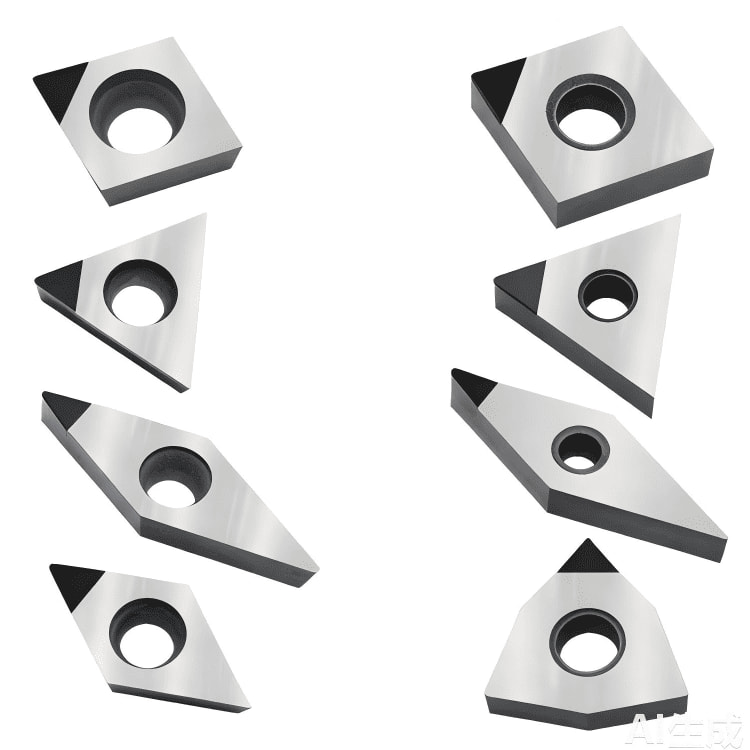
Blade Models: VCGT160404-2N, XRZW120402-1N Blade Models: VCGT160404-2N, XRZW120402-1N
Tool Material Grade:Alloy Blade PD01E
Cutting depth ap (mm): 0.5, 0.5
Per-turn feed rate (mm/rev): 0.005, 0.005
Cutting speed Vc (m/min): 300, 300
Tool Life (pieces/blade): 35, 420
Summary: Processing life (units/blade) increased directly by 12-fold.
PCD Reamers#PCD Tool#PCD Drills#PCD Milling Cutters