
Application checkWe review the drawing, material, hole requirements and current process.
PCD & CARBIDE CUTTING TOOL MANUFACTURER
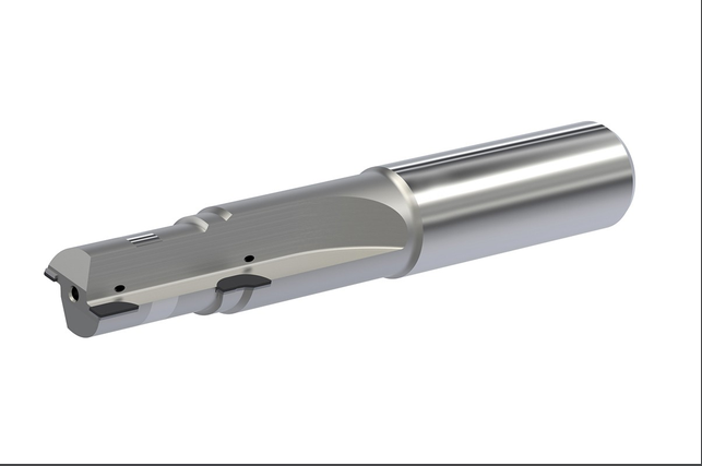
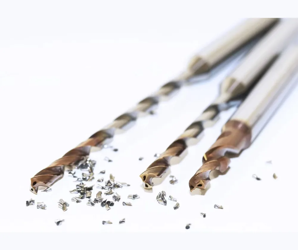
Custom PCD Reamers & Solid Carbide Drills
Engineered for automotive, EV and precision machining. Hole tolerance, runout and edge condition are held from sample through repeat supply.
- Custom EngineeringBuilt to Drawing
- About 3 WeeksSample Lead Time
- Factory-DirectTechnical Support
 Automotive & EV Components
CORE PRODUCT FAMILIES
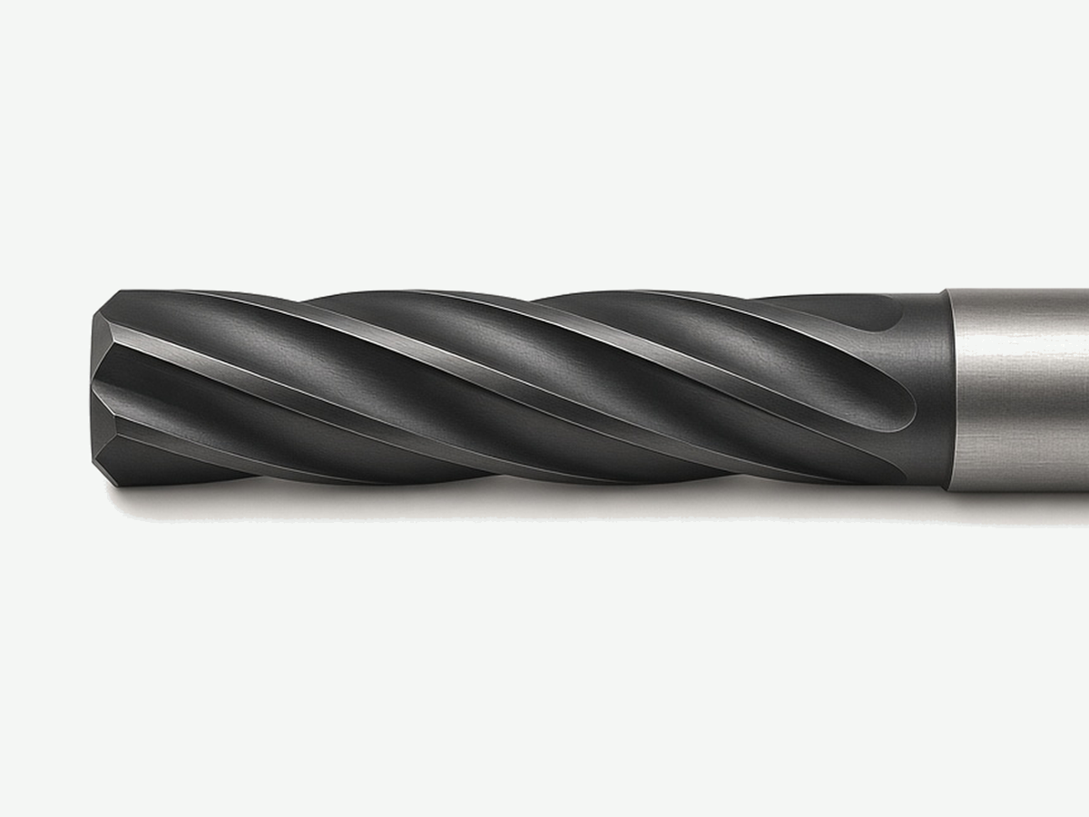
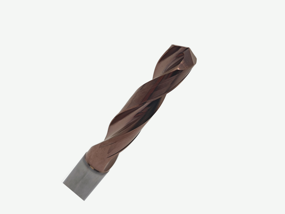
Four Tool Families for Precision Holemaking
Choose by the operation the hole needs — drilling, deep drilling or bore finishing — and by whether the workpiece is non-ferrous or ferrous. Each family carries its own selection criteria and inspection points.
MANUFACTURING & QUALITY
Built In-House. Documented Before Release.
Grinding, erosion, measurement and release stay with one team — no third-party handoff between stages.
- Grinding and erosion platforms — EWAG, WENDT and VOLLMER platforms cut PCD and carbide edges to the approved tool design.
- Three defined inspection points — Tool geometry, assembled runout and machined-part acceptance, measured on ZOLLER equipment.
- ISO 9001:2015, certificate on file — ZGTC22Q01715R0, valid through 2028-10-23; runout ≤0.002 mm where specified.

CHOOSE BY APPLICATION
Tooling Solutions for Critical Components
Start with the component and the machining challenge. Each route connects the workpiece, material and recommended tool platform.
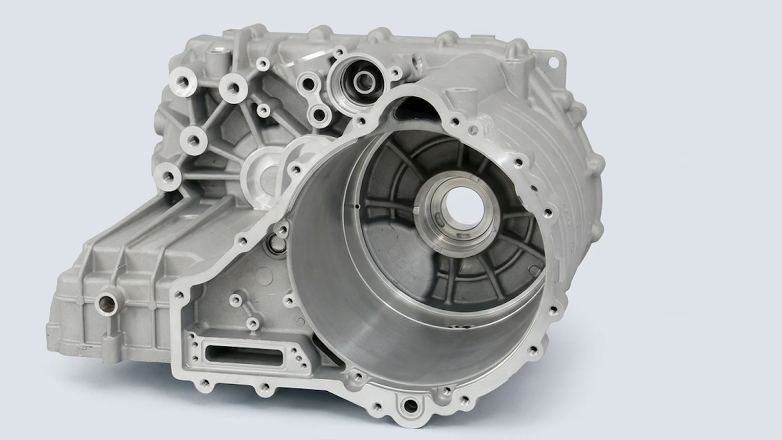
- Automotive Manufacturing — Cylinder heads, transmission housings, valve bodies. PCD reamers and custom tools.
- EV Components — Motor housings, battery-system parts and precision aluminum bores. PCD reamers and multi-step tools.
- Compressor Components — Scroll plates, housings and bores that need stable geometry. PCD form tools and reamers.
- General Engineering — Steel, stainless steel and mixed-volume precision holemaking. Solid carbide drills.
- Something else — Send the part drawing; the route is defined from the bore, tolerance and machine.
CHOOSE BY MATERIAL
Match the Tool to Workpiece Behavior
Material controls heat, chip formation, edge wear and surface response. Start with the grade, then match geometry, tool material and coolant.
- Aluminum Alloys — Surface finish and chip control. PCD reamers for housings and valve bodies.
- High-Silicon Aluminum — Wear control and hole consistency in abrasive cast alloys. PCD reamers.
- Steel — Heat control and chip evacuation in carbon and alloy grades. Solid carbide drills.
- Stainless Steel — Work hardening and thermal control. Solid carbide drills with matched edge preparation.
- Grade not listed — Send the grade, hardness, hole drawing and machine conditions for review.
CUSTOM TOOL ENGINEERING
From Drawing Review to Production-Ready Tool
Custom tooling runs as an engineering workflow — each stage fixes the inputs, decisions and deliverable.
- 01 Drawing & Application Review — Part drawing, material, tolerance, hole condition, machine setup and coolant.
- 02 Tool Concept & Quotation — Tool structure, cutting geometry, guidance, coolant route and interface.
- 03 Engineering & Manufacturing — Production drawings, tool body, cutting material and edge process.
- 04 Precision Inspection — Critical dimensions, runout, cutting-edge condition and defined inspection points.
- 05 Sample Validation & Repeat Supply — Trial results, wear and hole quality; specification frozen for reorders.

REAL APPLICATION CASES
Real Applications. Documented Engineering Decisions.
Anonymized customer case, structured around the machining problem, the tool strategy and the validation checkpoints.
Custom PCD combination drill-reamer for a 6061 aluminum brake valve body
- 01 Machining problem — Separate operations added tool changes and alignment risk between drilling and finishing.
- 02 Tool strategy — One custom PCD combination tool integrated the features around the drawing and machine interface.
- 03 Shop-floor outcome — Fewer tool changes, with validation focused on hole quality and repeatability.
- Validation checkpoints — Hole size, surface finish, tool wear, cycle stability.

TECHNICAL RESOURCES
Technical Guidance for Better Tool and Process Decisions.
Reference and checklists
- Cutting Tool Selection Handbook — Grades and coatings.
- PCD Reamer Inspection Pack — Geometry, runout, records.
- PCD Reamer RFQ Checklist — Data that speeds quotation.
Technical articles
- Tolerance, runout and finish — Setting the tool band for H7.
- Tool life & cost per hole — Price, tool changes, scrap risk.
- How to choose a solid carbide drill — Class, L/D, coolant route.
Reference only — results depend on tool design, workpiece and machine.

DISTRIBUTOR & OEM PARTNERSHIPS
A Technical Supply Partner for Repeat Business.
For cutting tool distributors, OEM buyers and machining solution providers that need custom capability and controlled specifications.
- For distributors — Product selection, drawing review, customer-specific quotations, sample plan, then an approved specification.
- For OEM buyers — Custom geometry, reviewable branding and packaging, documented revisions, repeat supply.
- For solution partners — Application data and process review, machine, holder and coolant interface checks, validation feedback.
- Partnership path — 01 Qualify the fit · 02 Pilot one customer application · 03 Build repeat supply.
- Start here — One drawing or current tool becomes a scoped proposal, sample plan and quotation.

QUICK RFQ
Send Your Drawing or Machining Requirement.
Share the application details that affect tool design. An HENTRY sales engineer can then review the requirement, identify missing information and define the next quotation step.
01
Part MaterialGrade, hardness or silicon content when relevant
02
Hole / Feature RequirementDiameter, tolerance, depth and surface finish
03
Machine & Current ProcessHolder, coolant, pre-hole and existing tool
04
Production ObjectiveCurrent issue, quantity, validation and target timing
Need to attach a drawing?
Email the drawing and reference your company or application.
zwx@xrzpcd.com
WHAT HAPPENS NEXT
A practical engineering review—not a generic sales reply
Missing details clarifiedAn engineer follows up only on the information needed to define the tool concept.
Suitable tool routePCD, carbide or another practical approach is considered against the application.
Reply within 1 business dayYou receive the next technical questions or quotation step without unnecessary delay.
NDA available on requestMention confidentiality requirements before sending restricted files.