
Start with the workpiece and the feature you need to produce. Choose the operation and tool construction, then match the cutting material, geometry, and coating to the actual setup. A useful shortlist names both a candidate and the condition that could rule it out. Confirm the choice through part inspection and a controlled machining trial before replacing an established production tool.
This HENTRY handbook is for process engineers, technical buyers, and cutting-tool distributors. It covers drilling, milling, turning, and precision holemaking at the selection stage. It does not provide universal cutting parameters and does not imply that every tool family discussed is available from HENTRY. Sawing, grinding, and specialist processes need their own application review.
Keep five descriptions separate: a drill is a tool type; solid or indexable describes construction; carbide is a cutting material; a corner radius describes geometry; and a coating describes a surface system. A supplier grade may combine substrate and coating information. These labels answer different questions.
Before selecting · Tool type by operation · Carbide vs HSS · PCD & other materials · Geometries · Coatings · Insert grades · Example · Validate · FAQ
What to Check Before Selecting a Cutting Tool
Use the six checks below as a traveler order, not as a catalog shortcut. Industry maps of workpiece groups and cutting-tool materials help you name what to record; they do not replace your drawing or machine limits. See this workpiece materials overview and this cutting tool materials overview for classification language only.
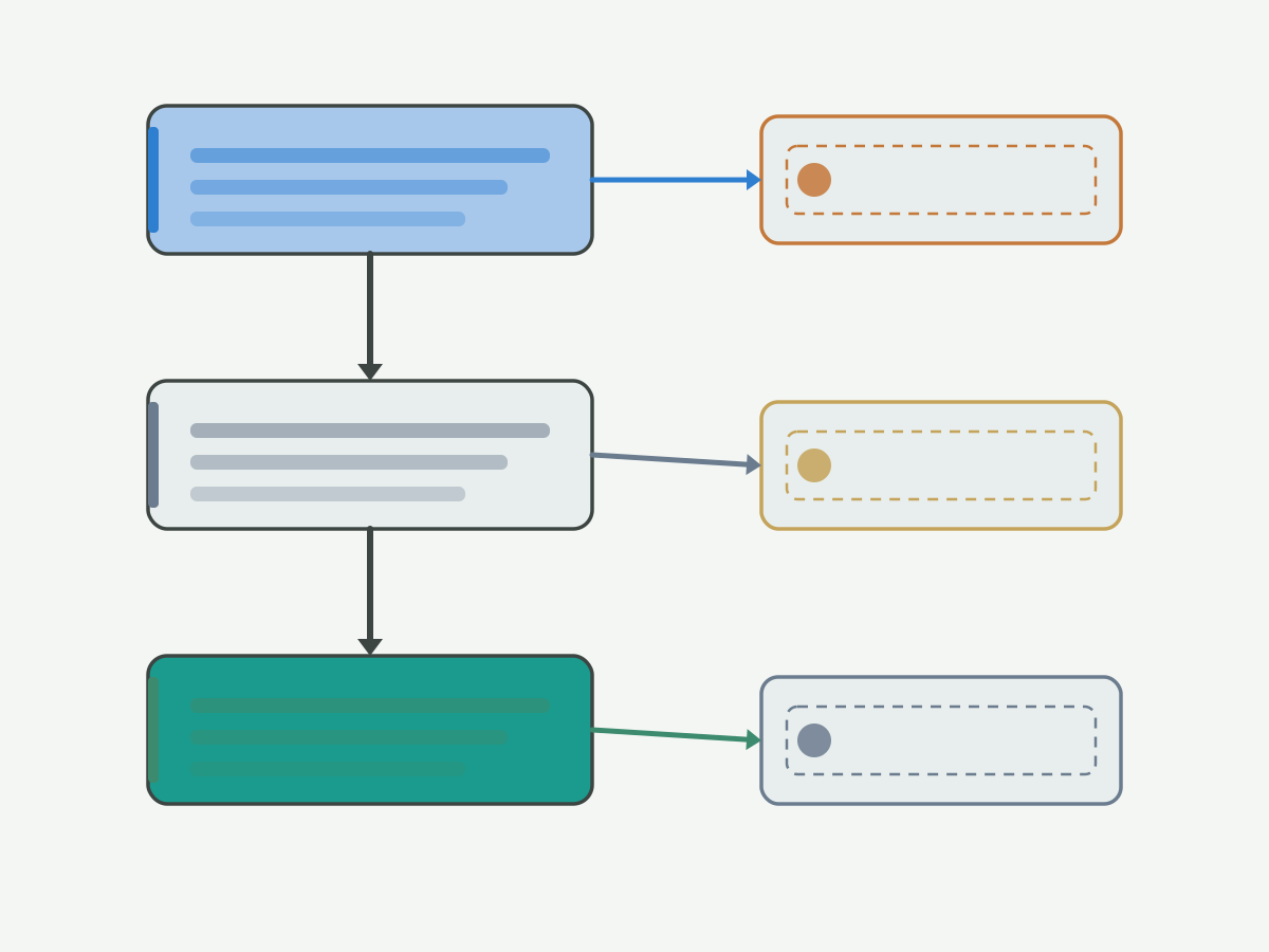
- Identify the workpiece. Record its designation, condition, and hardness where relevant, including whether the surface is cast, forged, or already machined.
- Define the feature. Mark the hole, slot, wall, contour, thread, or turned surface on the drawing. Include access and remaining stock.
- Set acceptance criteria. Specify dimensions, form and position requirements, surface condition, and burr limits, with the intended inspection method.
- Check the system. Record machine capability, holder, tool overhang, coolant delivery, chip evacuation, and fixture clearance.
- Build a shortlist. Select the tool family and construction, then compare material, geometry, and coating combinations approved for that task.
- Validate the candidates. Record quality, tool condition, actual cycle events, and cost on a consistent accepted-part or accepted-hole basis.
If the workpiece condition or acceptance criteria are unknown, obtain that information before specifying a final tool. If clearance, coolant, or an interface requirement cannot be met, revise the tool or process. Do not resolve a missing input by copying a default from another job.
Which Cutting Tool Type Matches the Operation
Match the task first, then the construction. A hole diameter alone does not determine the whole process. Define whether the operation must establish the hole, enlarge it, improve its size and finish, or correct its location. Public drill-selection structure that separates workpiece demands from tool-family choices is summarized in this drill selection overview. Milling cutter role literacy lives in this milling cutter selection overview. Neither page is an HENTRY stock list.
| Task | Candidate family | Next check |
|---|---|---|
| Create a hole in solid material | Drill or a separately approved holemaking strategy | Depth, entry, exit, and chip path |
| Finish an existing bore | Reaming or boring, according to the correction required | Pre-hole, stock, location, and form |
| Machine a pocket, wall, or contour | End mill, face mill, or dedicated profile tool | Access, profile, and permitted entry |
| Turn a diameter, face, or groove | Matching turning or grooving system | Holder, insert, and interruptions |
| Produce a thread | Tap, thread mill, or threading tool | Thread form, hole condition, and machine capability |
Do not assign hole establishment, enlargement, finish improvement, and location correction to a reamer without checking the pre-hole and process capability. Thread forming needs a separate material and pre-hole assessment; it is not simply a cutting tap with the same preparation. For form versus cut tapping on aluminum, use form tap vs cut tap. For reamer family literacy after the hole route is already finishing, use reamer types and materials. Broader metal drill type discovery lives on drill bit types for metal CNC.
Compare construction separately. A solid tool, a replaceable-head system, and an indexable tool have different interfaces and replacement procedures. Confirm the complete assembly, allowable reach, and inspection requirements. A compatible-looking insert or head is not evidence of a compatible mounting system. Indexable architecture deep dive stays on indexable tools guide. When a solid carbide drilling path is already justified by depth, entry, and chip path notes, check solid carbide drills. When diameter and productivity already point to another architecture, check indexable drills. Dedicated deep-hole systems stay on gun drilling guide when L/D pushes past ordinary twist-drill practice.
Carbide vs HSS and the Conditions That Change the Choice
HSS remains a candidate when a suitable drill must serve smaller batches or an application where toughness matters. Manufacturer drilling guidance often distinguishes conventional HSS, cobalt-alloyed HSS, and powder-metallurgy HSS. Their properties and intended uses are not identical. Identify the actual grade rather than treating every HSS tool as the same option.
Carbide also covers a range of grades. Grain structure and binder composition affect hardness and fracture behaviour; selecting the hardest listed substrate does not automatically select the most suitable tool. Cutting-material family boundaries (including HSS and cemented carbide) are framed in the cutting tool materials overview linked above. Deeper HSS versus cobalt versus carbide literacy for drills lives on drill bit materials HSS cobalt carbide. Stainless-specific drill shortlisting stays on drill bits for stainless steel.
| Condition | Candidate direction | Exclusion or next check |
|---|---|---|
| Small-batch drilling where toughness matters | Compare appropriate HSS grades with a carbide option | Actual material, tool limits, and accepted-hole cost |
| Repeated production with a documented wear issue | Evaluate a matching carbide configuration | System capability and measured quality over use |
For repeat production, compare a matching carbide tool with the current solution when tool wear, cycle time, or dimensional consistency creates a documented problem. Check whether the machine, holder, coolant, and inspection plan can support the candidate. For a small batch already meeting requirements, first establish what a change would actually improve. A lower purchase price or a longer nominal life alone cannot settle the decision.
An unstable setup still needs investigation. Treat toughness as a selection factor, not permission to accept a loose fixture or excessive runout. Ask the supplier for starting conditions for the exact tool, then validate within those limits. Do not transfer a drill recommendation to an end mill simply because both are made from the same material.
When to Compare PCD and Other Cutting Materials
PCD is a candidate for suitable non-ferrous or non-metallic machining tasks where abrasive wear is important. Conventional PCD is not the default choice for steel cutting because of its chemical interaction with iron at cutting temperatures. A material name alone does not establish that a particular PCD tool can handle the planned engagement.
PCD and diamond-coated carbide are different constructions. A sintered PCD blank typically uses a carbide substrate to support the diamond layer for subsequent tool manufacture. A deposited diamond coating on a carbide tool is a different surface architecture. Blank-maker construction notes that describe carbide-supported sintered diamond layers are useful as architecture literacy; see this PCD blank construction overview. A blank specification does not establish the performance, geometry, or service options of a finished HENTRY tool.
For an aluminium fit bore, compare a suitable carbide finishing tool with a PCD candidate only after defining alloy condition, pre-hole, stock, and acceptance criteria. Ask how each option will be inspected, changed, and, where available, reconditioned. Stop the comparison if either candidate cannot meet the required feature or mounting conditions. When a PCD reaming path is already justified, check PCD reamers.
CBN is associated with suitable hardened-steel finishing and some cast-iron operations. Ceramic families cover different application windows; thermal shock and fracture resistance need attention. Cermets are candidates for selected finishing tasks where wear and adhesion behaviour matter. These are separate application decisions, not a universal progression from cheap to premium tooling. For these families, request the specific workpiece range, operation, edge preparation, and coolant guidance. A grade intended for one turning condition is not automatically approved for interrupted milling. Inclusion here explains selection boundaries; supply and application support must be confirmed for any requested HENTRY product.
Which Geometries Match the Feature and Chip Flow
Geometry answers a different question from cutting material. Match the end profile, flute and chip space, reach, and permitted entry to the feature and the chip path you can actually clear.
End mill types for slots, walls, and curved surfaces
Square, corner-radius, and ball-nose end mills have different end profiles. The first retains a flat end with a sharp nominal corner; the second rounds the corner while retaining a central flat; the third has a rounded end. Match that profile to the required feature and the material that can remain after the tool path. End-mill selection checklists that keep material, operations, flute count, dimensions, and coating as separate questions include this end mill selection question checklist. Milling task hubs on HENTRY stay on milling tools guide.
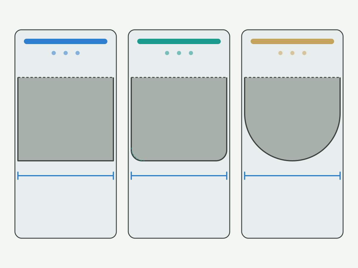
Start with a square-end candidate for a flat floor and wall task when its nominal corner matches the drawing. Consider a corner-radius candidate where the permitted transition allows it. For a curved surface, evaluate a ball-nose or corner-radius option with the actual contact and tool path. Check the remaining profile in CAM and then measure the part; the tool name does not establish the achieved surface quality.
Cutting diameter, flute count, length of cut, reach, and tool profile are separate end-mill selection inputs. More flutes are not a universal improvement, and an unnecessarily long cutting section is not a substitute for a suitable reach design. The tool must have enough access and chip space for the operation. Check whether the exact tool is approved for plunging, ramping, or helical entry before using those motions. Include the neck, holder, and fixtures in the clearance review. A flat end does not itself confirm centre cutting or an authorised entry strategy. Ramping and helical entry habits live on ramping and helical entry for end mills. After the profile match is written down, product families to check include carbide end mills, square end mills, corner radius end mills, and ball nose end mills. Face-milling bodies that are already justified by area removal belong on indexable face milling cutters.
Drill and reamer geometry for hole requirements
For a drill, identify the point design, flutes, margins, and coolant arrangement. Record the actual entry surface and exit condition, including cross-holes and interrupted exits. Ask for a geometry intended for those conditions instead of selecting only by diameter. Solid-carbide geometry deep dive lives on solid carbide drill geometry. For a reamer, define the pre-hole size and form, stock distribution, and support before requesting the final tool geometry. Reaming process literacy that keeps pre-hole and allowance discipline visible includes this reaming process overview.
If the hole is out of position, determine which preceding operation establishes location. A finishing tool cannot be assumed to recover every upstream error. The inspection plan must distinguish size, form, position, and surface requirements rather than treating a successful diameter reading as proof of all four. Chip evacuation and coolant path choices that affect geometry selection are organized in this chip control overview.
Insert geometry and edge preparation
Specify the insert shape and size, seating interface, clearance, corner geometry, and chip-control design. Identify edge preparation separately. Ask for the application range of the proposed combination, including the planned feed and depth of cut. An insert can fit a pocket yet remain unsuitable for the intended cut. Edge-preparation literacy that treats hone and chamfer as controllable edge states includes this edge preparation overview. Turning insert selection discipline stays on turning insert selection. When the turning path is already justified, check turning tools and cutting inserts.
When an edge chips, inspect mounting, engagement, and the damage pattern before changing grade. When a worn region grows gradually, document that progression and part quality. Wear-pattern literacy that helps you describe edge state without inventing life percentages includes this tool wear understanding overview. These observations help frame a supplier discussion; they do not identify a unique mechanism without the process history. Symptom triage that is already a fault problem stays on CNC machining troubleshooting.
How to Select Tool Coatings
PVD and CVD describe deposition processes. TiN, TiCN, and titanium-aluminium nitride coatings describe chemical families rather than a complete tool specification. Substrate, coating, and edge condition must be considered together. The same family name does not establish identical performance across suppliers.
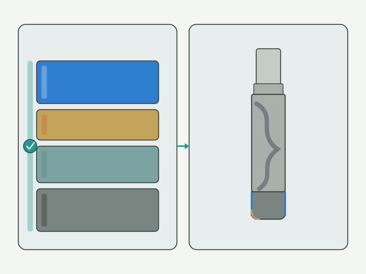
Begin with the workpiece and the proposed tool. Obtain the coating designation and applicable operations, then check coolant conditions and the intended edge preparation. Use the supplier’s approved combination as the candidate. An uncoated tool remains an option when its particular geometry and application data support the task; coating should not be added merely because it sounds more advanced. Drill coating literacy (not a color ranking chart) lives on drill bit coatings explained.
DLC means diamond-like carbon and must not be used as another name for crystalline diamond coating. As one concrete third-party instance, a coating-house ta-C product sheet for specified non-ferrous and polymer applications states that colour can vary with geometry and application; see this ta-C coating system example. Neither the appearance nor that product’s test results proves the identity or performance of another coating, including any HENTRY coating.
Before ordering, ask: Which substrate is being coated? What is the exact coating system? Does the finished edge meet the required geometry? What changes after regrinding or recoating? If a tool wears unexpectedly, preserve its identification and photographs before changing the coating specification. Do not use a new coating to bypass a known clearance or chip-evacuation problem. For wear signals, shop-record tool life, regrind versus replace, crib inventory and supplier selection on cost per accepted part, see tool life and tooling economics.
How Insert Grades Relate to Workpiece Groups and Operations
Workpiece groups organise the first search: P for steels, M for stainless-steel applications, K for cast irons, N for non-ferrous materials, S for superalloys and titanium, and H for hard materials. These labels do not replace the actual alloy and condition. Some material subtypes require more specific classification; check the selected supplier’s application data. ISO-style application material group education is summarized in this ISO application material groups overview.
An insert designation and a supplier grade answer different questions. Record the full order reference, geometry, and grade, not just a familiar colour or a short material-group label. Supplier codes are not a universal interchange standard. A replacement requires checks of both the assembly and the cutting application. Turning insert choice structure that keeps geometry and grade as separate fields includes this turning insert selection overview.
Use the workpiece group to find the relevant catalogue section, then narrow by operation, roughing or finishing duty, interruptions, cooling, and stability. Request the exact document revision behind the recommendation. Do not transfer an insert-grade chart directly to a solid carbide drill or end mill: the complete tool and engagement still need their own specification. Threading method choice (cut, form, mill) belongs on its own traveler fields; method literacy includes this threading method selection overview.
Example: Tool Selection for an Aluminium Housing
Illustrative selection scenario, not an HENTRY production test: a housing requires a pocket with walls, mounting holes, and a fit bore. The drawing identifies the features but supplies no approved cutting parameters here. Material grade, condition, stock, and inspection limits must be filled in before tool selection is released.
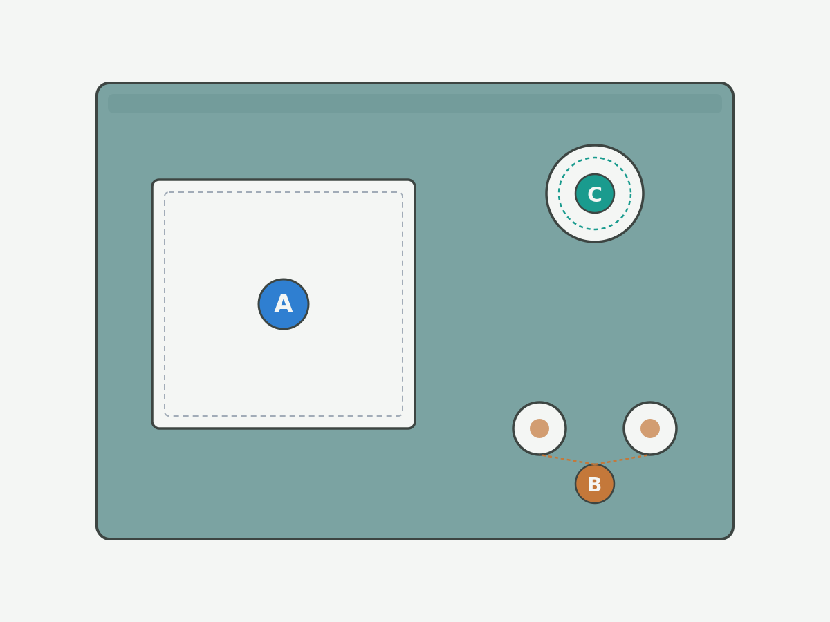
For feature A, begin with the required floor and wall transition. A square-end or corner-radius milling candidate remains open until the corner requirement, pocket access, and entry method are checked. For feature B, select a drill family after confirming hole depth, exit condition, and coolant access. For feature C, establish the pre-hole and finishing stock before comparing a suitable carbide or PCD reaming candidate; use a different process if the required correction cannot be assigned to reaming.
| Feature | Candidate decision | Evidence before release |
|---|---|---|
| A Pocket and walls | Select end profile and reach | Drawing transition, clearance, and surface inspection |
| B Mounting holes | Select drilling construction | Depth, exit, coolant, and hole inspection |
| C Fit bore | Compare feasible finishing routes | Pre-hole, stock, size, form, and finish |
The useful outcome is a separate decision record for each feature. It is not a claim that the housing needs one cutting material everywhere. Evidence that the pocket mills satisfactorily does not validate the fit-bore process. Each feature must pass its own inspection requirements before the complete part is accepted.
Selection Summary by Conditions and Next Checks
| Condition | Candidate direction | Exclusion or next check |
|---|---|---|
| Suitable abrasive non-ferrous finishing | Compare a PCD candidate with the feasible carbide baseline | Material compatibility, edge loading, and finished feature |
| Flat floor with a specified corner transition | Choose an end profile that matches the drawing | Permitted radius, access, and residual material |
| Curved-surface finishing | Evaluate ball-nose or corner-radius contact | Tool path, accessibility, and measured profile |
| Insert chipping before the intended tool change | Investigate engagement and mounting, then shortlist geometry and grade | Do not substitute wear resistance for diagnosis |
| Coating choice without a clear application record | Request the exact coating and substrate combination | Do not identify coating from colour |
Use this table to choose the next check, not to issue an order without a specification. Where more than one candidate remains, compare the same accepted result and document the conditions that would change the decision.
Procurement Checklist for a Cutting Tool Enquiry
- Workpiece designation, condition, relevant hardness, and raw-surface state.
- Drawing revision and marked features, including access, depth, and remaining stock.
- Size, form, position, surface, and burr requirements with inspection methods.
- Operation and its responsibility: roughing, finishing, hole creation, or final sizing.
- Machine, holder and interface, actual overhang, available coolant, and chip removal.
- Current tool reference, geometry, grade, and coating where known; current parameters and issues.
- Photographs or records showing the tool condition and affected feature, if replacing a problem tool.
- Batch size, repeat demand, trial scope, and agreed acceptance criteria.
- Required replacement parts, identification, traceability, and reconditioning arrangements to confirm.
Distributors should also identify the intended customer applications, specification coverage, and required documents. Clarify packaging, marking, and repeat-supply requirements in the enquiry; do not assume that every option is included. Keep unknown items marked as unknown instead of inventing a value to complete the form. This checklist does not invent SKU lists, MOQ, prices, or lead times.
What to Validate Before Replacing the Current Tool
First establish why a change is being considered. Record whether the problem is rejected parts, wear, breakage, an unavailable specification, cycle time, or supply continuity. Keep a functioning current tool as the baseline when possible. If the problem comes from an incorrect setup, correct that before crediting a new material or coating with the improvement.
Agree the drawing revision, material batch, setup, inspection method, and withdrawal criteria before the trial. Use suitable approved settings for each candidate; fairness does not require forcing different tools to use identical parameters. Record all changes. If geometry, coating, and parameters change together, the result evaluates the combination, not the isolated effect of the coating.
Inspect the same defined features and record tool condition at comparable stages. Stop according to the approved procedure if damage, chip blockage, unsafe contact, or a quality limit is encountered. Record the event and revise the proposal before resuming. A short successful trial supports further validation; it does not establish repeat production capability across all batches.
For economics, choose one denominator: accepted holes for a holemaking operation, or accepted parts for a complete part comparison. Record tool consumption and eligible reconditioning, actual machine time, change-related downtime, and non-duplicated quality costs over the same production interval. Keep one-time qualification costs visible. Do not count a tool change both inside cycle time and again as separate downtime, or count labour twice if it is already included in the shop rate.
If the proposed benefit disappears after these costs and constraints are included, retain or optimise the current solution. If it remains credible and acceptance criteria are met, expand validation with the responsible production and quality teams. Keep a practical rollback route until the replacement is released.
Discuss Your Cutting Tool Selection with HENTRY
Bring HENTRY a defined task: a drilling requirement, an end-mill profile choice, a precision-bore problem, or a proposed combination holemaking operation. Provide the drawing and the constraints from the checklist. Ask which exact tool configurations can be supplied and which application details still require confirmation. The material families in this handbook do not constitute a stock list.
For a new project, include material, feature and quality requirements, machine conditions, and quantity. For a replacement, add the current specification, tool photographs, and what has already been tried. A useful enquiry subject is “Cutting tool selection: material, operation and feature”. Agree how drawings will be transferred through the available contact channel.
Discuss Your Cutting Tool Selection with HENTRY
The enquiry begins a specification discussion. Confirm the scope of supplier support and retain responsibility for the machine program, inspection, and production release within the agreed project process. No fixed life improvement, lead time, price, or file-upload capability is assumed here.
Cutting Tool Selection FAQ
Is carbide always better than HSS?
No. Compare actual tools on the same task. A suitable HSS drill can remain a candidate where batch size and toughness matter. A carbide candidate needs appropriate application conditions. The decision should survive a quality and accepted-hole or accepted-part cost comparison, not just a material ranking.
Can one cutting material cover every operation on a part?
It may be possible, but it is not the starting assumption. A pocket, a mounting hole, and a fit bore have different feature and inspection requirements. Build the shortlist by operation and retain a common material only where it is justified.
Is PCD the same as diamond-coated carbide?
No. PCD is a sintered diamond material used in cutting elements, often with supporting carbide in the blank construction. A diamond coating is deposited on a substrate. Confirm the finished tool and its application data before comparing them.
Can a coating compensate for unsuitable geometry?
No. A coating does not make an inaccessible feature reachable or provide a missing chip path. Resolve geometry, assembly, and engagement requirements first, then evaluate a coating combination with evidence for the task.
Are insert grades interchangeable between manufacturers?
Do not assume so. Match the insert and holder interface, geometry, application range, and complete order reference. A similar grade label is not a verified cross-reference. Qualify the proposed replacement on the defined operation.
What is the minimum information for a reliable recommendation?
Start with material and condition, the marked feature and acceptance criteria, machine and holding conditions, coolant, and quantity. For a bore, add pre-hole information. For a contour, add access and radius requirements. Include current damage and process records when solving a failure.
How do I confirm the choice on my component?
Use a documented baseline, suitable candidate settings, and agreed inspection and withdrawal criteria. Compare tool condition and accepted output over the planned trial. Expand validation only after the responsible team accepts the results and the remaining production risks.
Sources and Related Selection Tasks
The outbound references support material, geometry, coating, and selection-structure explanations cited in the body. Manufacturer-specific data remain tied to their own products. The selection workflow, feature example, and enquiry checklist are HENTRY editorial decision aids, not measured performance results. Sources checked for this draft on 19 October 2026 (Asia/Shanghai).
- Workpiece materials overview (third-party education page; linked in body)
- Cutting tool materials overview (third-party education page; linked in body)
- Drill selection overview (third-party education page; linked in body)
- Milling cutter selection overview (third-party education page; linked in body)
- End mill selection question checklist (third-party education page; linked in body)
- PCD blank construction overview (third-party blank-maker page; linked in body)
- ta-C coating system example (third-party coating-house page; linked in body)
- Reaming process overview (third-party education page; linked in body)
- Chip control overview (third-party education page; linked in body)
- Edge preparation overview (third-party education page; linked in body)
- ISO application material groups overview (third-party education page; linked in body)
- Turning insert selection overview (third-party education page; linked in body)
- Threading method selection overview (third-party education page; linked in body)
- Tool wear understanding overview (third-party education page; linked in body)
For the next decision, use the relevant product or Knowledge link inside the sections above. Narrow the enquiry to a feature before requesting a model. When specifications are fixed, use the procurement checklist and validation section to prepare the quotation and trial requirements. For end-milling spindle speed, feed rate, chip load and chip-evacuation checks after a candidate tool is framed, see speeds, feeds and chip control. For tool condition monitoring, adaptive cutting boundaries and unattended-production readiness after the tool path is stable, see AI and automation in CNC machining.