
What Are Coolant Holes in a Carbide Drill?
Carbide drill coolant holes—also called internal coolant channels or through-coolant passages—carry cutting fluid from the spindle and holder through the drill body. Outlets near the point deliver fluid directly to the cutting zone.
This addresses three common production problems:
- External coolant cannot reach the tip. As the drill enters deeper into the workpiece, the hole wall blocks an external jet.
- Chips cannot leave the hole reliably. Internal flow can support chip transport back through the flutes when the chip shape and flute space are suitable.
- Heat and adhesion build at the cutting edge. Fluid arriving close to the lips can improve cooling and lubrication compared with a jet that only wets the tool outside the hole.
Internal coolant does not guarantee a successful process. Users still report packed chips, burnt margins, unequal outlet flow and drill breakage when the pump, filtration, holder, flute geometry or cutting data do not match the hole. The first question is therefore whether coolant reaches the point with enough usable flow. The second is whether the internal channel layout fits the drill geometry.
Use the Through-Coolant Carbide Drill Guide when the main question is whether internal coolant is needed. Continue here when the application already needs internal delivery and the remaining decision is how the passages should run through the carbide body.
Start with the Drill Geometry, Not the Channel Name
Coolant holes are formed inside the carbide rod before the drill flutes and point are ground. Their position must therefore remain compatible with the finished tool geometry along the complete cutting length.
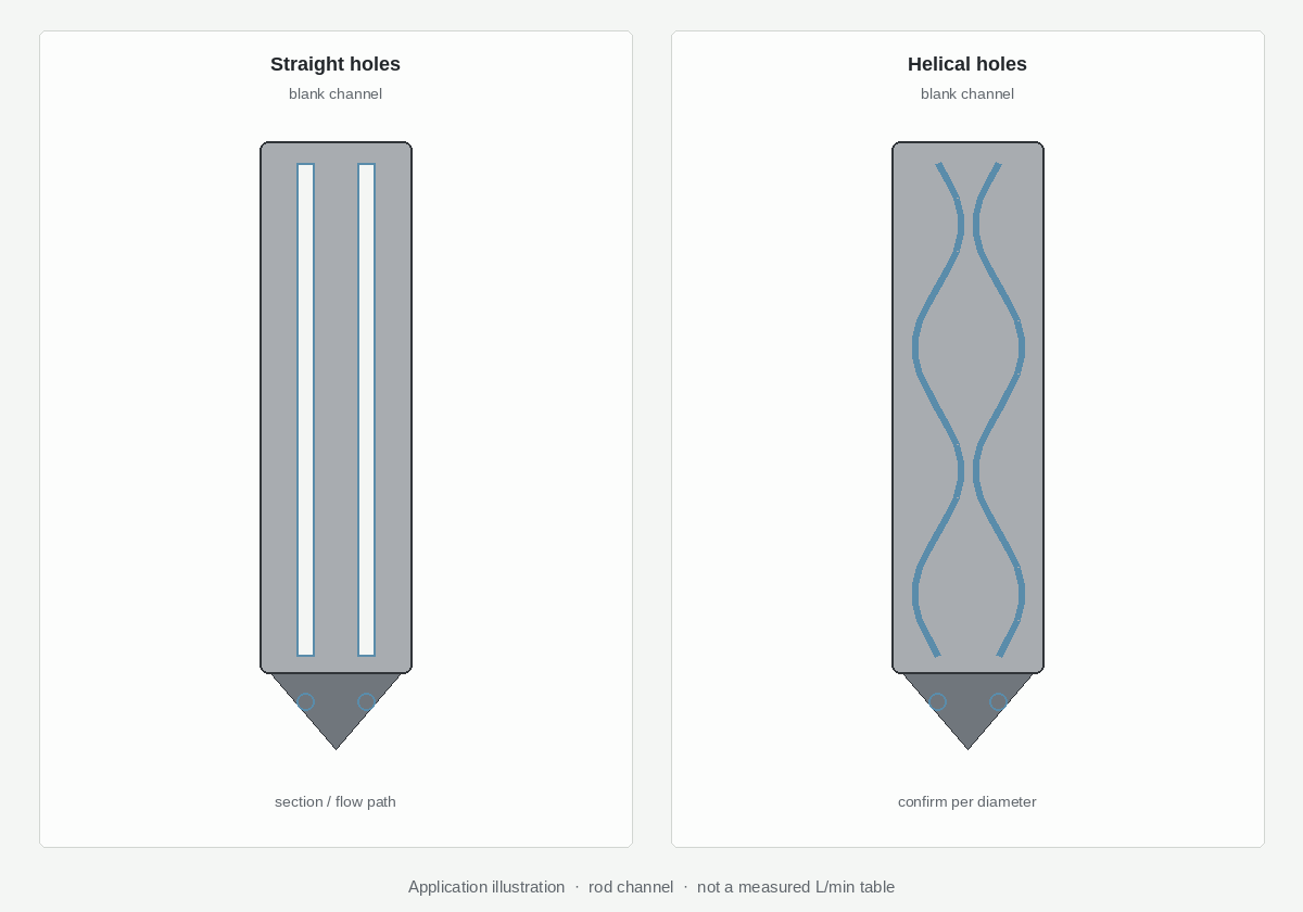
A straight channel stays at one angular position relative to the blank axis. A helical channel changes its angular position along the tool length. That difference affects where the channel sits beneath the lands, how it avoids breaking into a flute during grinding, and where it can exit at the drill point.
Do not confuse three separate decisions:
| Decision | Question it answers | Where to continue |
|---|---|---|
| Through-coolant or external coolant | Must coolant reach the cutting zone through the tool? | When Flood Coolant Is Not Enough |
| Straight or helical internal channels | How should the passages run through the carbide body? | This guide |
| Flute, point and margin geometry | How will the drill cut, guide and evacuate chips? | Solid Carbide Drill Geometry |
The machine must still deliver coolant through the spindle, holder and tool. The blank configuration cannot compensate for inadequate supply, a leaking interface or a blocked filter.
Straight and Helical Coolant Holes Compared
| Design factor | Straight coolant holes | Helical coolant holes | What the engineer must confirm |
|---|---|---|---|
| Channel path | Axial path through the blank | Rotating path with a specified helix or pitch | Complete path, channel count and exit position |
| Relationship to flutes | Fixed angular position; must remain inside usable carbide after flute grinding | Can follow the rotating land pattern of a twist drill | Flute helix, core profile and minimum remaining wall |
| Flow path | Shorter and easier to model when diameter and finish are equal | Longer curved path; pressure loss cannot be inferred from the word “helical” | Channel diameter, roughness, length, fluid and actual pressure/flow |
| Tip outlets | Central, parallel or offset exits depending on the design | Outlet clocking changes with channel pitch and tool length | Which cutting edge or chip pocket each outlet must serve |
| Blank availability | Common central and parallel patterns are broadly available | Available in multiple helix angles, but not every diameter, grade or length is stocked | Current supplier range, minimum quantity and lead time |
| Grinding flexibility | Suitable when the fixed channels stay clear of the flute and margin geometry | Useful when the channels must track twisted lands or a defined outlet location | Grind allowance and risk of opening a channel into a flute |
| Inspection | Check channel location, continuity and finished outlet | Also check helix/pitch relationship and outlet clocking | Approved blank and tool drawing revision |
This table describes design tendencies. It does not establish a performance ranking. Two tools with different channel layouts may deliver similar results when their channel area, outlet direction, pump supply and cutting geometry are correctly matched.
When Straight Coolant Holes Are a Practical Choice
Straight channels deserve consideration when a central or parallel passage can remain inside the drill body without interfering with the finished flutes.
They are often practical when:
- A central channel suits a single-flute, gun-drill-style or special tool concept.
- Two parallel channels can reach the required point outlets while preserving sufficient carbide around the core and lands.
- A common blank diameter and grade are available with the required channel configuration.
- The tool geometry or delivery schedule benefits from a simpler, established blank route.
- The application does not require the channels to follow a high-helix land through the complete cutting length.
Straight does not mean “low performance.” A correctly sized straight passage can supply the cutting zone effectively. The engineer still needs to confirm the position of the channel relative to the flute root, the minimum ligament of carbide, and the outlet geometry at the point.
When Helical Coolant Holes Should Be Evaluated
Helical channels should be evaluated when the internal passages need to rotate with the drill body or when a defined channel-to-land relationship is required along the cutting length.
They may be appropriate when:
- A twist drill has long helical flutes and fixed straight channels would approach or break into the flute root.
- The outlets must arrive at defined positions near two or more cutting edges or chip pockets.
- The available carbide blank series is designed around a specified flute helix and channel pitch.
- The drill diameter, length and grade fall within a confirmed helical-blank range.
- A custom drill drawing can freeze channel orientation, pitch, flute geometry and finished length together.
The helix must match the finished tool, not simply look similar in a blank catalogue. Changing tool length or regrind position can change outlet clocking. The toolmaker therefore needs the exact blank specification and the finished drill drawing before grinding begins.
Coolant Flow: Why Helical Does Not Automatically Mean More Flow
Available pressure at the machine is only one part of the system. Flow reaching the drill point also depends on:
- Channel hydraulic diameter and total cross-sectional area
- Channel length and internal surface condition
- Curvature, transitions and outlet restrictions
- Coolant viscosity and temperature
- Filtration and contamination
- Spindle, rotary union, holder and sealing losses
A helical passage is longer than a straight axial passage through the same tool length. If channel diameter and surface condition were otherwise equal, the longer curved route can add resistance. A helical design may still work better in the finished drill when it permits a larger usable passage, protects the channel from flute grinding or directs the outlet more effectively. That is why layout must be assessed as a complete tool rather than by channel name alone.
Ask for pressure and flow at a defined test point where possible. “The machine has 40 bar” does not prove the same flow reaches two small drill outlets after losses through the spindle, holder and channels.
Body Strength Depends on the Minimum Remaining Carbide
Every coolant hole removes load-bearing material from the drill body. The critical question is not whether the path is straight or helical; it is how much carbide remains at the weakest section after the flutes, margins, relief and channels are all present.
Review:
- Channel diameter and number of channels
- Bolt-circle or radial position of the channels
- Core thickness and flute depth
- Minimum ligament between a channel and the flute root
- Minimum ligament between adjacent channels
- Local section at steps, necks and point transitions
- Working projection, holder runout and expected torsional load
With straight channels, the weakest angular section repeats along the cutting length. With helical channels, the channel position rotates, so the minimum ligament can occur at a different axial location. Neither arrangement should be described as stronger without the complete cross-section and loading condition.
If breakage occurs, inspect the fracture origin. A crack beginning beside a coolant passage suggests a different investigation from a tip chip caused by entry impact or a mid-flute break caused by chip packing. Use the Stickout, Runout and Toolholder Guide before assigning every body failure to the coolant-hole layout.
Match the Channel Layout to Hole Depth and Chip Behavior
| Application condition | Design implication | Do not assume |
|---|---|---|
| Short, accessible through hole | Either channel style may work if outlets cover the edges and the blank suits the geometry | Helical channels are automatically necessary |
| Moderate or high L/D | Coolant delivery and chip transport become more sensitive to channel area, outlet position and flute capacity | Channel layout alone replaces a validated deep-hole cycle |
| Blind hole | Outlet direction, bottom clearance and the return path for chips and coolant need review | More pressure always clears the bottom |
| Small drill diameter | Channel size, remaining web, filtration and blockage risk become tightly linked | A catalogue pressure value proves usable flow |
| Ductile, stringy chips | Flute volume, chip shape, feed and coolant delivery must work together | Helical coolant channels fix unsuitable chip formation |
| Cross hole or interrupted exit | Coolant can control heat and carry fragments, but the edge still sees mechanical interruption | Internal coolant removes impact risk |
For execution details at higher L/D, continue to the Deep-Hole Carbide Drilling Guide. If chips pack even though coolant reaches the point, use the Carbide Drill Chip-Packing Checklist.
Manufacturing and Supply Limits
Carbide blank suppliers offer central, parallel and helical coolant channels in multiple grades and dimensions, but their ranges are not interchangeable. Availability depends on the combination of:
- Finished drill diameter and blank diameter
- Carbide grade
- Channel count, diameter and radial position
- Helix angle or pitch
- Blank length and finish condition
- Ground or as-sintered supply
- Minimum order and delivery time
The finished drill diameter alone is insufficient. Grinding stock must be considered, and a requested helix must remain compatible with the final flute helix and drill length.
XRZ therefore treats coolant-channel construction as confirm per diameter and application. A quotation should identify the proposed route as straight, helical or pending blank confirmation. Availability and stock are confirmed at quotation; they are not implied by a generic product image.

Diagnose Problems Before Changing the Channel Layout
| Symptom | First checks | When channel geometry enters the review |
|---|---|---|
| Weak flow from both outlets | Pump setting, filter, spindle/holder leakage and blocked passages | If the confirmed supply cannot pass the required flow through the selected channel area |
| Uneven outlet jets | Partial blockage, outlet grinding, channel continuity and holder alignment | If one passage has a different path, restriction or exit position |
| Chips pack at depth | Chip shape, feed, peck strategy, flute volume and return path | If outlet direction or available channel area cannot support evacuation |
| Burn marks or margin pickup | Coolant reaching the edges, recutting and contact length | If outlets miss the active zone or flow is restricted near the point |
| Break beside a coolant passage | Runout, projection, chip torque and fracture origin | If the remaining carbide ligament or channel location is insufficient |
| Tip chipping at entry or interruption | Entry geometry, workholding, pilot condition and impact | Only after mechanical entry conditions are controlled |
Changing from straight to helical channels without identifying the failure mechanism can reproduce the same problem in a more expensive blank.
How XRZ Reviews a Through-Coolant Carbide Drill
XRZ manufactures drawing-based solid carbide drills and reviews the complete holemaking system before confirming a coolant-channel design. The review includes the workpiece material, hole diameter and depth, blind or through condition, flute and point geometry, machine and holder, available coolant supply, chip behavior, current failure mode and inspection requirement.
For the currently published product range, XRZ supports custom solid carbide drills with through-coolant options for suitable CNC applications. The exact straight or helical blank, diameter, length and delivery status are confirmed during quotation. Sample validation should then verify chip evacuation, edge condition, hole quality and process stability under the customer’s actual setup.
View Through-Coolant Carbide Drills · View Custom Solid Carbide Drills
Information Required for Channel Selection
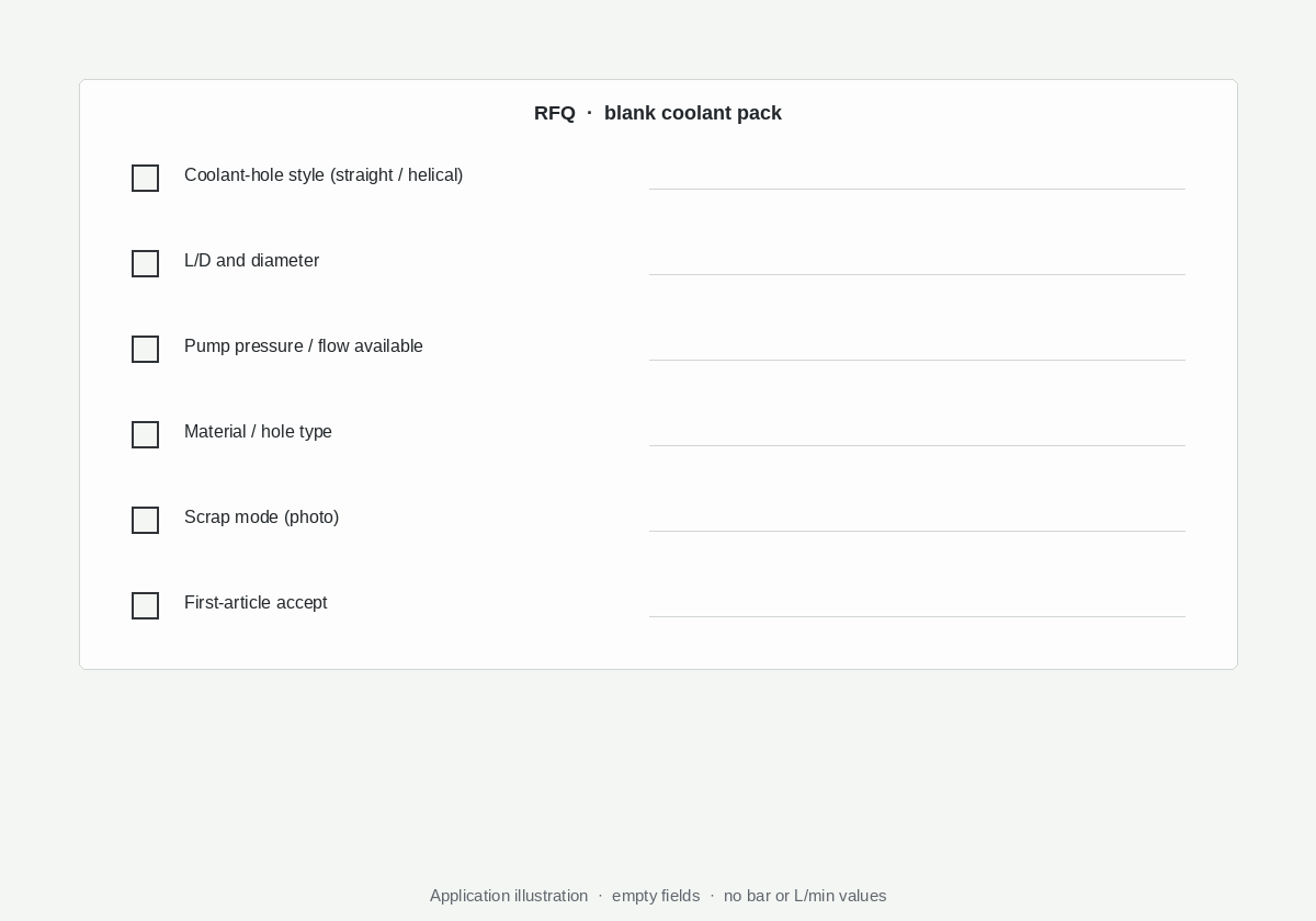
Send the following information before requesting “straight” or “helical” as a fixed specification:
- Component drawing and revision
- Hole diameter, full-depth dimension and calculated L/D
- Blind, through, cross-hole or interrupted condition
- Workpiece grade, hardness and condition
- Flute/point requirement if already controlled by the drawing
- Machine, spindle interface, holder and working projection
- Through-coolant capability, pressure and flow where known
- Coolant type and filtration level where known
- Current drill, cutting data, chip form and failure photographs
- Required quantity, repeat demand and target delivery
If a value is unknown, mark it as unknown. XRZ can keep the recommendation conditional rather than assuming a pump, blank or flute geometry that the production setup cannot support.
View the Solid Carbide Drill RFQ Checklist · Submit a Custom Cutting Tool RFQ
Frequently Asked Questions
Are helical coolant holes better than straight coolant holes?
Not in every drill. Helical channels can remain aligned with twisted lands and support planned outlet positions. Straight channels offer a direct axial route and may be the more practical blank for suitable geometries. Compare the complete drill cross-section, flow system and supply range.
Do helical coolant channels provide more flow?
Not automatically. Flow depends on channel area, length, roughness, restrictions, coolant condition and the complete machine-to-tip delivery system. A helical path is longer, but it may enable a more useful outlet or passage size in a particular drill design.
Can straight coolant holes be used in a twist drill?
Sometimes. The fixed channel positions must remain inside the carbide lands after the helical flutes are ground, and the finished outlets must serve the cutting zones. The usable result depends on drill diameter, core and flute geometry, channel position and cutting length.
Does internal coolant eliminate peck drilling?
No. Internal coolant can improve cooling and chip transport, but the cycle still depends on L/D, chip formation, flute capacity, material and machine conditions. Establish the deep-hole process separately.
What limits helical coolant-hole availability?
The carbide grade, blank diameter, channel count and size, helix angle or pitch, length, finish condition and current supplier stock all matter. XRZ confirms the proposed blank against the exact drill drawing at quotation.
What should I send XRZ for a custom drill recommendation?
Send the component drawing, material, hole diameter and depth, hole type, machine and holder, available coolant data, current chip or breakage evidence, volume and acceptance requirements.
Request a Coolant-Channel Review
Choose the coolant-hole layout from the finished drill and the production process, not from a blank photograph. Send the hole drawing and machine conditions so XRZ can review straight, helical or another through-coolant construction and confirm the available blank before sample manufacture.
Submit the Hole Drawing · Explore the Solid Carbide Drill Technical Center
Written by: Kevin Zeng, CEO, XRZ Precision
Engineering review: Jiack Liu, Engineering Director
Review scope: Solid carbide drill coolant-channel selection, blank availability, strength, flow and application inputs.
Draft updated: September 27, 2026