
Product Detail
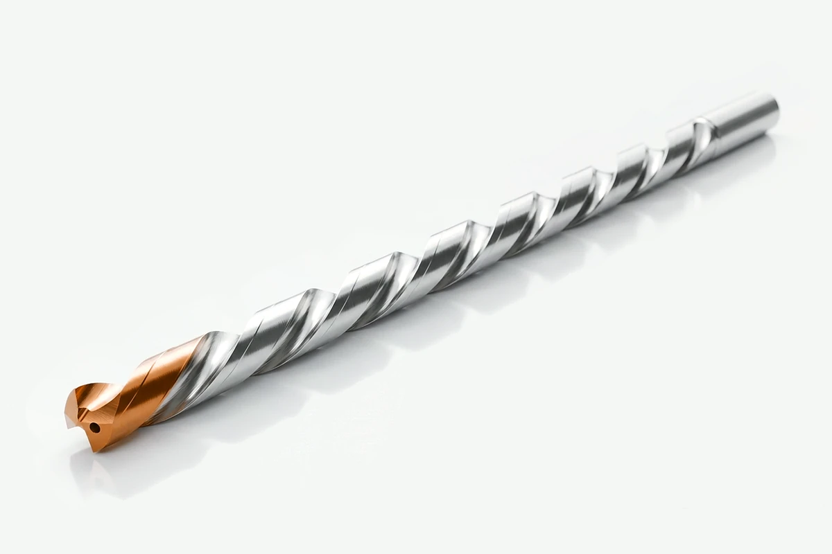
Deep-Hole Carbide Drills (High L:D) for CNC
Solid carbide deep-hole drills ground to drawing for long CNC holes, with recorded HENTRY applications and the inputs needed for an RFQ.
Solid carbide · Deep holes · High L:D
Deep-Hole Carbide Drill Series for Long CNC Holes
Most deep-hole jobs reach us with the same history: the hole measures well near the entry, then the long section walks, rubs the wall or snaps the drill. A correct diameter at the entry says little about the bottom of the hole, so we select the drill together with the feed strategy, the coolant route and the retract method.
HENTRY grinds solid carbide deep-hole drills to customer drawings. Whether a long hole runs reliably depends on usable depth, the chip path out of the hole, coolant reaching the cutting edge and how the finished bore will be measured. Tool length alone does not settle the question. Material, diameter, usable depth, hole type and coolant supply are the inputs we review first.
Request a deep-hole drill quote
Jump to: Depth · Materials · Entry and exit · Coolant · Troubleshooting · Inspection · Design and manufacture · Application records · Specifications · RFQ inputs · FAQ
Signals that depth owns the failure
- The finished depth on the print, or the L:D it implies, is the main process risk on the part.
- Your team is already weighing a pilot hole, a peck cycle or through-coolant for this hole.
- The hole is a long passage in an automotive, hydraulic, mold or fixture component.
- Current drills wander, rub the wall or break before anyone has a complaint about diameter.
When another HENTRY drill fits better
- The hole is shallow enough for a standard-length drill: compare the options in our carbide drill bit series overview.
- Depth is moderate and coolant delivery is the only open question: start from the coolant section below, which leads to our through-coolant range.
- The goal is a precision bore finish in aluminum after drilling: a PCD reamer for the finishing pass is the better route.
Long drill or deep-hole process? Define the depth you actually need
L:D tells you how demanding a hole is. It does not tell you whether a longer drill will run it. Before length is settled, we look at guidance at the start, the distance chips must travel, coolant at full depth and how the finished bore will be measured.
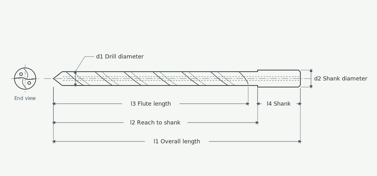
Measure the depth the part really needs. On a blind hole, keep the usable cylindrical depth separate from the depth to the drill point. On a through hole, include the exit wall and anything the drill or holder could meet on the way. Stick-out is measured from the holder face, and overhang the hole does not require only adds deflection. On the drawing, keep drill diameter d1 and shank diameter d2 apart from overall length l1, reach to shank l2, flute length l3 and shank length l4. Reach to shank tells you whether the holder clears the part; the depth the drill can actually cut is set by flute length less the room chips need to leave the flutes, and we confirm it on the drawing. A quote built on overall length alone can end up with more stick-out than the hole needs.
A long solid carbide twist drill and a gun drill are not interchangeable at the same diameter and length, and our guide to L/D, peck strategy and chip escape in deep-hole carbide drilling explains where a solid carbide drill reaches its limit and another process takes over.
How deep-hole drilling changes by workpiece material
Each material fails in its own way as the drill goes deeper. Send the exact alloy, condition and hardness; the priorities below start our review and do not fix one geometry or coating for a whole material family.
| Workpiece material | What gets worse with depth | What we check | How the solution is set |
|---|---|---|---|
| Carbon and alloy steel | Chips lengthen or compact in the flute, and spindle load climbs as the drill advances. | Chips from the first millimeters against chips from the failure depth, plus grade and hardness. | If the symptom follows depth, we work on chip breaking and flute space before blaming wear. |
| Stainless steel | Tough chips are hard to move over a long stroke, and dwell or rubbing hardens the wall locally. | Edge condition, every pause or re-entry in the cycle, and whether coolant flow stays continuous. | We set an edge and a cycle the drill can run without extra stops added by trial and error. |
| Aluminum alloys | Built-up material and a large chip volume can choke the exit path. | Alloy and temper, adhesion on the drill and scoring near the bottom. | Scoring at the bottom is treated as a sign of chips recirculating, so flute space and lubrication are reviewed together. |
| Cast iron (gray and ductile) | Fine particles collect at the bottom and edge wear builds; gray and ductile iron behave differently. | Iron type and grade, filtration and how the edge wears over the batch. | Short chips still have to be cleared from the bottom, so evacuation and filtration stay in the review. |
| Titanium alloys | Heat concentrates at the cutting edge while the chip path gets longer. | Alloy, treatment, coolant access and edge condition in controlled trials. | Steel cutting data is not carried over, and an existing drill is not pushed deeper without validating the application. |
| Heat-resistant alloys, including nickel-based | Wear and heat build up together over a long evacuation path. | The exact alloy designation; "superalloy" is not enough to quote from. | Geometry, coolant and the tool-change criterion are set in an agreed trial; results from a shorter hole or another part are not transferred. |
Where the material causes trouble at any depth, the stainless steel carbide drill range, the aluminum carbide drill range and our notes on drilling gray and ductile cast iron go into more detail.
Entry, bottom, exit and cross-holes: plan the sequence before programming
Flat, inclined or curved entry
An asymmetric entry can push the drill off line before the long body has any support. Decide whether the surface needs preparing or a pilot hole is required. If a pilot is specified, its diameter, depth, angle and tolerance must suit the long drill; a hole made by another drill of the same nominal size does not qualify as a pilot. Our article on pilot holes and entry control for carbide drills covers spot and pilot choices. Follow the tool's entry and retract procedure, and never rotate a long drill at working speed until it is guided.
Deep blind holes
Chips have to travel back up the full depth to the entry. Separate the geometric bottom from the functional depth, and decide how residue will be removed when the cycle ends. If the hole will be tapped or will take a seat later, put the required clearance and cleanliness on the drawing before reach is chosen.
Through holes and inclined exits
Support under the cutting edges changes as the drill breaks out. Note the exit wall, its angle and any burr limit. The breakout section has to be reviewed in the actual program, since no fixed feed reduction suits every part. Our guide to inclined entries, cross holes and thin-wall exits goes further on support and exit feed.
Cross-holes and internal cavities
An intersection interrupts the cut and, deep in the part, can redirect both coolant and chips. Mark on a section view where each crossing starts and ends. A drill proven in a continuous hole is not automatically suitable for the crossing, so operation order, tool compatibility and access for deburring and inspection all need checking. For drill-and-finish routes through intersecting holes, see cross-hole drilling and finishing.
Continuous feed or peck cycle. A peck cycle does not fix every deep hole. Some drills need a defined sequence, others run continuous feed under set conditions, and every retract changes guidance, re-entry and contact with chips left in the hole. Confirm what the drill allows and how chips will leave before choosing a CNC cycle; our note on when peck drilling is actually required covers that decision.
Coolant: what actually reaches the bottom of the hole
No single pressure value suits every diameter, and the pump rating says little about what arrives at the cutting edge. We review the whole supply chain: available flow, fluid, filtration, the machine connection, the passage through the holder and the channels in the drill. Run checks with safe methods, never open a pressurized circuit, and observe the process with the machine guards closed. If the machine only has external coolant, say so at the start of the RFQ, because coolant visible at the entry does not prove that it reaches the edge as depth grows. Supply checks are set out with our through-coolant carbide drills; the flood-versus-internal decision is covered in when through-coolant is required on solid carbide drills.
The hole starts well and fails deeper: depth-indexed troubleshooting
Record the depth and moment at which each symptom appears; that figure separates an entry problem from an evacuation, bottom or retract problem. If load, noise or chip flow changes abnormally, stop the trial safely and do not force the feed to final depth.
| When it appears (by depth) | Hypothesis to check first | Diagnostic step before repeating |
|---|---|---|
| From the first few millimeters, the hole drifts further off line as depth grows | Initial direction, misalignment, overhang or workpiece movement. | Check the pilot and the setup, then measure position at several depths; a correct entry position does not prove straightness. |
| At the same depth on every hole, load rises | Chip build-up, insufficient reach, or a local feature in the part. | Match that depth to the drawing, cross-holes and flute length; inspect chips and coolant supply, and confirm the program stays within usable depth. |
| In the deep section, the wall shows scoring or poorer finish | Trapped chips, rubbing, or wear on the cutting edges and margins. | Locate the defect relative to any retract, then examine residue and tool marks with the machine stopped before touching the feed. |
| At a cross-hole or at the exit, the drill chips or breaks | Loss of support, or a change in cutting and coolant conditions. | Mark the point on a section of the part and plan a dedicated strategy for that zone; the continuous-hole cycle is not carried over automatically. |
| On retract or re-entry, the drill breaks | Re-entry incompatible with the pilot, retained chips, or a wrong tool path. | Review the whole sequence, including rapid moves and the guidance conditions the tool requires. |
| Over the batch, tool life drops from drill to drill | Changes in coolant, filtration, material or setup condition. | Compare records drill by drill (depth, pieces, chips, rejection criteria, maintenance) and change one variable per trial. |
Verifying diameter, straightness and cleanliness to the bottom
Agree the inspection plan before the first batch is made. Diameter, axis straightness and hole position are three separate requirements, and the measuring method has to reach the zones that matter with enough capability for the drawing tolerance.
First article
Check the entry, the middle section and the bottom or exit, as access allows. A plug gauge that only enters the first part of the hole says nothing about the rest of it. Where the bore cannot be reached directly, agree a method in advance; that may mean dedicated gauging or a sectioned validation part, with your approval. When the hole is a fluid passage or will take another operation, also check cylindrical depth, internal burrs and loose residue.
Repeatability and cost per accepted hole
Track how hole quality changes over each drill's life, in addition to counting holes until breakage, and set a change criterion that includes wear and tolerance drift. When you judge cost per accepted hole, weigh full cycle time, retracts, inspection and rejects alongside tool cost. If the bore needs a finishing operation, plan it at drill selection: a longer drill does not remove that step or secure the final tolerance on its own.
How HENTRY designs and manufactures deep-hole carbide drills
The further the edge works from the entry, the harder it is to clear chips and carry heat away, and a slender body bends and vibrates more easily. We design each deep-hole drill around its guidance and coolant supply from the first concept.
Flute form and rigidity
We adapt the parabolic flute profile to the hole depth and to the chip size and shape we expect, so there is room for evacuation while the core keeps the stiffness the reach demands. The cutting edge is ground to balance centering, chip formation and chip breaking against edge strength.
Carbide substrate and coolant channels
The substrate used for these drills balances toughness and hardness, with a cobalt content of 12–15% and a grain size below 0.4 μm. Coolant channels are controlled for pitch regularity, diameter and symmetry. The exact carbide grade is confirmed for the drill we quote.
Grinding and process control
Our deep-hole drills go through between-centers grinding, cylindrical grinding, CNC tool grinding and edge preparation. On a long tool every grinding step shows up at the tip, so we control finished geometry along the body as well as the cutting diameter. The grinding process includes measures that reduce the effect of residual stress on dimensional stability. Photos of our grinding and inspection equipment are collected under manufacturing and quality evidence.
Coated zone length
Coating is chosen for heat resistance, wear and surface finish, and we adjust the length of the coated zone to the drill configuration. A longer coated zone is not applied by default; its extent has to suit the geometry and the work the drill will do.
Five HENTRY deep-hole drilling records: conditions and tool life
The five records below come from HENTRY application files. Tool life stays in the unit each job was measured in: pieces, meters machined or hours. The cases are not directly comparable with one another, and actual results vary with material, machine, setup, coolant and operating conditions.
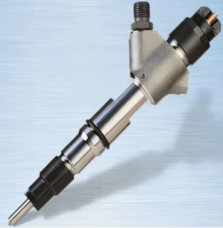
Case 1 · High-pressure injector body in 1215 steel
| Field | Record |
|---|---|
| Part | High-pressure injector body |
| Goal | Meet the cycle time, avoid drill breakage and improve tool life |
| Material | 1215 steel |
| Hole Ø × depth | Ø6.105 mm × 92 mm |
| Machine | Horizontal machining center |
| Coolant | Internal + external |
| Speed | 2,000 rpm |
| Feed | 80 mm/min |
| Recorded result | 1,000 pieces |
Tool life exceeded the customer's expectation.
Case 2 · High-pressure injection pump body in aluminum alloy
| Field | Record |
|---|---|
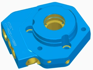
| Part | High-pressure injection pump body |
| Goal | Tool life of about 500 m |
| Material | Aluminum alloy |
| Hole Ø × depth | Ø4.3 mm × 93.5 mm |
| Machine | Vertical machining center |
| Coolant | Internal + external |
| Speed | 2,000 rpm |
| Feed | 120 mm/min |
| Recorded result | 800 m (recorded limit life) |
Stable tool life exceeded the customer's target. The 800 m figure is the recorded limit life and is not a recommended tool-change interval.
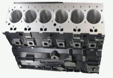
Case 3 · Diesel engine block in HT280
| Field | Record |
|---|---|
| Part | Diesel engine block |
| Goal | Meet the cycle time, avoid drill breakage and reach at least 350 pieces |
| Material | HT280 |
| Hole Ø × depth | Ø6 mm × 185.4 mm |
| Machine | Horizontal machining center |
| Coolant | Internal + external |
| Speed | 3,200 rpm |
| Feed | 384 mm/min |
| Recorded result | 400 pieces |
The recorded life meets the target of at least 350 pieces.
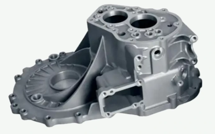
Case 4 · Transmission (gearbox) housing in QT600-7
| Field | Record |
|---|---|
| Part | Transmission (gearbox) housing |
| Goal | Stable tool life of 100 m with no drill breakage |
| Material | QT600-7 |
| Hole Ø × depth | Ø6.05 mm × 109 mm |
| Machine | Vertical machining center |
| Coolant | Internal + external |
| Speed | 2,200 rpm |
| Feed | 120 mm/min; peck Q2 (as recorded for the case) |
| Recorded result | 120 m |
Tool life exceeded the 100 m target. The Q2 peck code has to be read with the control and program of this application and is not a universal instruction.
Case 5 · Surgical forceps in medical-grade stainless steel
| Field | Record |
|---|---|
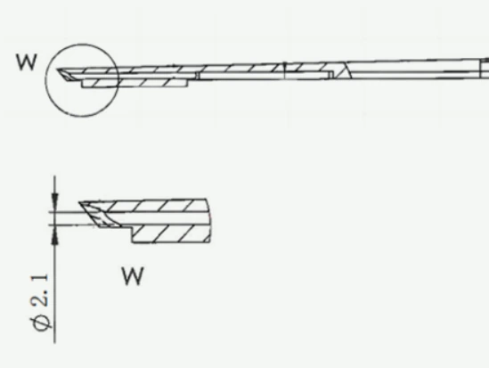
| Part | Surgical forceps |
| Goal | Stable tool life of 7 hours |
| Material | Medical-grade stainless steel (grade not specified) |
| Hole Ø × depth | Ø2.1 mm × 30 mm |
| Machine | Dedicated vertical machining center |
| Coolant | Emulsion, internal coolant |
| Speed | 2,000 rpm |
| Feed | 100 mm/min |
| Recorded result | 7 hours stable life |
The HENTRY drill replaced the imported reference tool previously used in this operation. The record covers a machining result and does not constitute a medical-device certification.
To compare a record with your own process, start with the number of holes per part and your end-of-life criterion. A life in meters does not translate directly into a number of parts, and recorded hours cannot be turned into cutting time without knowing the cycle.
Deep-hole drill specifications: standard, custom and engineering-confirmed
| Parameter | Standard range | Customizable range | To be confirmed by engineering |
|---|---|---|---|
| Carbide substrate | Cobalt 12–15%, grain size <0.4 μm | Grade selected for the workpiece material | Exact grade, confirmed with the quoted drill |
| Coolant supply | — | Internal, external or combined supply, reviewed per application | Number and layout of coolant channels, confirmed in drawing review |
| Flute and cutting edge | — | Flute form and edge preparation adapted to depth and chip form | Point angle and helix angle, confirmed in drawing review |
| Coating | — | Coating and coated-zone length matched to drill configuration and workpiece | Specific coating, confirmed in drawing review |
| Length and shank | — | Special lengths and shanks reviewed from the drawing | Maximum length and L:D, confirmed in drawing review |
| Diameter | — | Made to the drawing | Diameter range and tolerance, confirmed in drawing review |
What engineering needs for high L:D quotes
- Material: grade, condition and hardness, noting whether the drilling zone is hardened.
- Diameter and its tolerance.
- Usable depth as measured on the drawing, plus the depth to the drill point on blind holes.
- Hole type: blind, through, or with cross-holes.
- Coolant supply (internal, external or both), machine, holder, stick-out and any known runout.
- Quantity and target date.
- For drift or section analysis: a section drawing with the straightness and position requirements.
- For a replacement comparison: the current drill, its cutting data, the failure mode and the depth at which the failure appears.
A one-line enquiry can start the review:
"Material [ ], Ø[ ] mm, usable depth [ ] mm, hole [blind / through / with cross-holes], coolant [ ], machine [ ]. We need to improve [chip evacuation / straightness / tool life / cycle time]."
For the remaining fields used in drawing review, work through our solid carbide drill RFQ checklist.
Deep-hole RFQ FAQ
What depth counts as "deep" for this series?
We judge it by the L:D of the hole and the section where the failure appears, without a fixed cut-off. If depth is already causing wander, rubbing or breakage, send the drawing and the usable depth and we review the hole as a deep-hole job.
Do you supply gun-drill systems?
Our deep-hole series covers solid carbide twist drills. A gun drill works within a separate system of guidance, coolant and chip evacuation, so the two cannot be swapped directly. When L:D, straightness or machine conditions are the limit, we first review the complete process for the hole.
We only have external coolant. Can a deep-hole drill still be quoted?
Yes, the hole can still be reviewed, as long as the limit is stated at the start of the RFQ. Coolant seen at the entry does not show what reaches the edge as depth grows, so depth, material, cycle and drill configuration are reviewed against that supply, and a different process setup may be proposed for the hole.
Can the hole be drilled from both sides to shorten the reach?
It can be evaluated. The deciding points are axis alignment and position where the two holes meet, the step or burr at the junction and how that zone will be inspected. Mark the datums and the requirements for the meeting zone on the drawing, especially if the hole guides a component or carries fluid.
Can an existing hole be used as the pilot?
Only after its diameter, depth, angle and tolerance have been checked against the long drill. A worn, misaligned or wrongly sized pre-hole does not guide the drill the way a pilot specified for the system does.
Can I order a special length or shank?
Special lengths and shanks are reviewed from your drawing. Send the part drawing together with the usable machine stroke, the holder and the stick-out available. Maximum length, stock and delivery are not assumed in advance; they are confirmed for the drill we propose.
Have the depth and stick-out on the drawing?
Send the part drawing with usable depth, material and coolant supply, and our engineers review the drill, the cycle and the inspection plan for that hole.