
How to Drill Inclined, Curved, Cross-Hole, and Thin-Wall Exits with Solid Carbide
Opening
The spindle starts on a cast incline, the point skates half a flute before it bites, and the corner is already white. Or the wall at exit is 1.2 mm of aluminum and the burr flips like a hinge. Or the create path opens into a cross bore and the lips unload—then reload on a sharp edge. Scrap photos look like “grade,” but the contact was never stable—and the programmer needs one map for entry walk, breakthrough shock, and thin-wall flex, not three OEM pages.
This page owns inclined and curved entry, thin-wall exit, and the cross-hole breakthrough window for solid carbide—plus the three-in-one decision map SERP rarely keeps on one URL: point, margin, feed, and support at those contacts, plus RFQ sketch fields. It does not rewrite the full interrupted-cut checklist (interrupted cut / cross-hole), general exit breakout & burr control, or pilot / entry control. Flute and point-angle stay on 2 vs 3 flute and point angles.
Answer box
Unstable first contact (incline / curve) and weak exit (thin wall / cross breakthrough) are where corners chip and burrs explode—often before “the grade is wrong.” Spot or flat-bottom, reduce entry feed, mill a flat when a conical point still walks, support the exit when you can, and match point / margin to the contact type. Send an entry/exit sketch, wall thickness, and failure photos. XRZ reads the contact with you, writes first-article accept before metal, and stays on first-off (sample validation · drill RFQ checklist → Custom Cutting Tool RFQ).
1. Condition map: incline / curve / cross breakthrough / thin-wall exit
Four contacts need different levers. This is an engineering heuristic map (inference), not a measured SFM or life table. OWN gain vs single-theme SERP: read all four on one card before you swap grade.
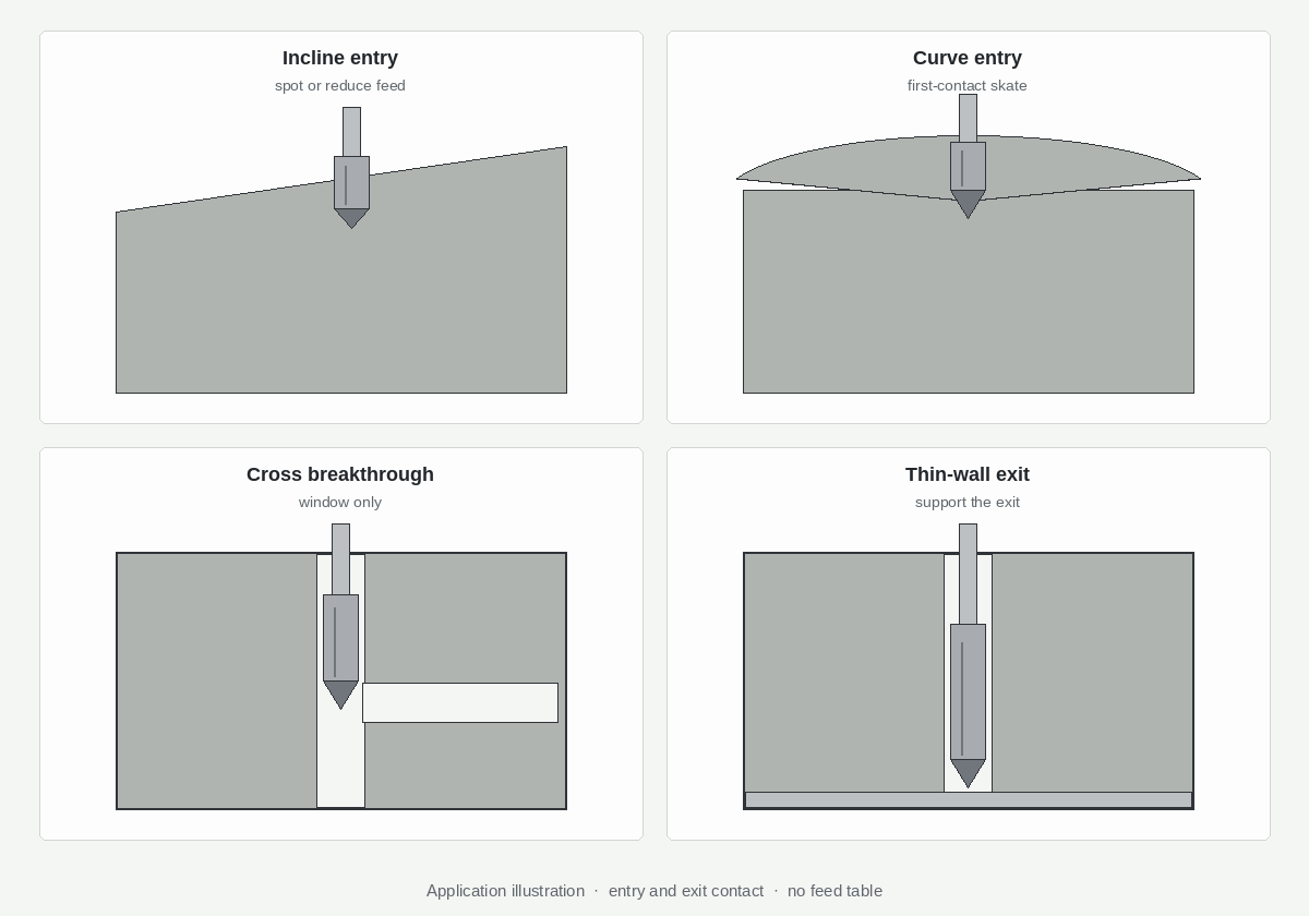
| Condition | Main risk | Prefer first | When to custom / escalate | Soft handoff |
|---|---|---|---|---|
| Inclined entry | Walk, one-lip load, corner chip at first bite | Spot or controlled approach; lower entry feed until full Ø engages; short rigid stickout | Cast angle + hard skin; repeated corner chips after feed cut; incline steep enough that mill-flat or flat-bottom enters the RFQ | Pilot / entry · point angles |
| Curved / irregular face | Point follows contour; bellmouth; margin rub | Short spot; flatten or fixture pad if allowed; do not chase with high entry feed | Contour radius ≈ drill Ø; no flatten on print | Pilot · breakage |
| Cross-hole breakthrough | Sudden unload / reload; lip chip in one revolution | Breakthrough window—feed plan across the open; edge that tolerates shock; chip clear at junction | Large window vs Ø; scrap only at intersection clock | Full interrupt → interrupted / cross-hole (do not rewrite) |
| Thin-wall exit | Hinge burr, wall flex, exit corner chip | Back-up / sacrificial support; exit feed or dwell; chamfer / lead before free hinge | Plant stiffness judgment on scrap (not a universal mm rule); free exit into air | Exit breakout |
Three-in-one read (OWN): if the same casting has incline entry and a thin exit and a cross window, do not pick one OEM “flat drill” slogan and ignore the other two contacts. Write which contact scraped first, then stack: entry control → breakthrough feed → exit support. Grade last.
Dedupe: full interrupted create load stays on interrupted-cut / cross-hole. This page owns the breakthrough instant plus incline / thin-wall contacts.
No absolute RPM/bar table here. Mid-depth packing or L/D → deep-hole · through-coolant.
2. Inclined & curved entry: walk, first-contact load, when to mill a flat
Inclined and curved faces punish a point that expects a flat start. One lip cuts while the other is in air; radial load walks the tip; corners chip before margins support. Curved and cast faces add a moving contact line along the contour.
First-contact (inference): walk/skate → one-lip overload until both lips engage → high-side margin rub. Carbide corners hate that shock more than HSS.
Feed and rigidity (tendency—validate on Ø and machine):
- Drop programmed feed for the first diameters until both lips are fully engaged; write the length—do not leave “operator feel.” OEM irregular-surface guidance often cites a substantial entry-feed cut (commonly discussed around ~25–33% of normal feed until full Ø engages)—OEM-published inference, not an XRZ measured table.
- Prefer short stickout and a rigid holder; long projection amplifies walk.
- Do not raise SFM to “bite harder” on a skating incline—that usually whites the corner faster.
When to mill a flat (inference, not a universal law): OEM guidance often treats roughly >10° incline (solid carbide, standard conical point) as the zone where milling a local flat—or switching to 180° flat-bottom—beats hoping a catalog point self-centers. Use that as a starting discussion threshold, then confirm on angle, skin, fixture, and scrap photos. Below it, spot + reduced entry feed may hold; above it, keep mill-flat / flat-bottom / custom point on the RFQ even if the buyer only asked for a harder grade.
Scrap that points to entry, not grade: chips only on first 0.5–2× Ø; bellmouth on the high side; white corners with mid-flute still sharp; walk into position error before depth. If the drill snaps after entry is stable → breakage overview.
3. Spot, pilot, flat-bottom — choose the entry tool path
Pick the tool path, not only the finish-drill brand.
Spot vs pilot vs when spot is not enough
- Spot: marks center and reduces skate. Match spot angle to the finish point so you do not leave a shoulder—detail on pilot / entry.
- Pilot: when depth, L/D, or alignment need a true pilot Ø—that page’s OWN process; this page only decides whether incline contact needs a controlled start.
- When spot alone fails: steep incline, cylinder OD, cast convex/concave, or contour radius near drill Ø—spot may center the tip while lips still meet unequal metal. Escalate to mill-flat, fixture pad, flat-bottom, or special point.
Flat-bottom / special point as entry (and exit-burr) lever
A flat-bottom carbide drill changes first-contact area on incline, curved plate, thin plate, and half-hole work. SERP sells the consolidator hard; XRZ treats it as a geometry option, not a universal incline cure.
Use when the print forbids a deep cone, a standard point still walks after spot + feed cut, or thin-plate exit needs flatter breakthrough (validate; no percent claim). It does not cancel bad fixture, oversize stickout, or a breakthrough that still needs a feed plan. Point/flute → flutes & point angles.
Decision order: contact type → spot/pilot? → mill-flat allowed? → standard vs flat-bottom vs custom → then grade. Reverse that and you buy a “stainless series” with the same skating entry.
4. Thin-wall exit: support, chamfer, exit feed
Thin-wall exit is not thick-section breakout into free air. The wall flexes; the ligament hinges; the exit corner unloads against a moving wall. General burr diagnosis → exit breakout; this section owns thin wall as a stiffness problem.
Workpiece support / sacrificial backing
When process allows, keep the wall from hinging:
- Fixture pad / clamp on the exit face near the hole.
- Sacrificial backing (scrap plate, soft-jaw insert, temporary plug) so the drill exits into support instead of air.
- Adjacent solid on castings—orient breakthrough into a thicker boss when the print permits.
Without support, feed and point alone often lose on thin walls. Call out whether back-up is allowed—that changes the RFQ more than “through hole.”
Chamfer, lead, and exit feed
Write exit feed / dwell / opposite-side approach when wall thickness is on the print—do not copy thick-wall exit feed onto a 1 mm aluminum wall. A controlled chamfer or exit lead can cut the hinge before create finishes (edge-prep vocabulary on the exit-breakout page; here the lever is stiffness + sequence). Coolant that clears the slug helps; delivery limits → through-coolant—no invented bar/L/min as XRZ measured.
Sketch must-confirm: wall thickness, free vs into-pocket, burr callout, back-up allowed, hinge photos (not only the lip).
5. Cross-hole breakthrough window only
When the create path opens into a side bore, lips unload then reload on the far edge. That breakthrough window is where many corner chips start—even if the rest of the hole is continuous.
This page owns: scrap clock at the intersection; feed plan across the open (OEM interrupt practice often cuts feed substantially while crossing—validate on window-to-Ø; no universal peck recipe); chip clear at the junction; edge/margin for one-revolution shock (plant validation, not a life claim); larger/shorter path first when diameters differ and process allows.
Does not rewrite: multi-window load map → interrupted cut / cross-hole. Soft-link when scrap shows a pattern of windows. Create + finish ream: send both scrap modes (drill lip at breakthrough vs reamer land after); the cross-hole drill-and-ream application path covers both steps. Coolant across an open intersection → through-coolant.
6. RFQ pack + service loop (entry/exit sketch → written accept → sample stay)
A harder grade will not flatten the incline. Useful path:
- Receive entry/exit sketch (incline/curve, wall thickness, cross-window clock), scrap photos, material, Ø × depth, coolant, stickout/runout if measured.
- Write acceptance: walk/bellmouth limits, exit burr, corner photo after breakthrough, position.
- Sample / first-off stay: run agreed checks; freeze offsets and tool revision before volume (sample validation).
RFQ fields: entry type (flat / incline angle / curve / cast skin) · exit type (thick / thin-wall thickness / free / into pocket) · cross-hole window size, clock, breakthrough vs multi-interrupt · spot / pilot / flat-bottom / mill-flat tried · scrap mode and location · material, Ø, depth, blind vs through · machine / holder / stickout · coolant flood vs through (unknown pressure = say unknown) · lip and part photos · first-article accept lines in writing.
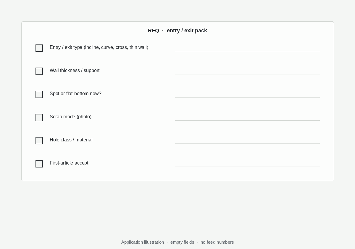
→ Drill RFQ checklist → Custom Cutting Tool RFQ. Product: Solid Carbide Drill · Flat-Bottom Carbide Drill.
Frequently Asked Questions
Do I always need a spot drill on an incline?
No. Steep incline, cast skin, or repeated walk/corner chip make spot or controlled approach a strong first lever. Shallow angles with rigid fixture and a self-centering point may start without a separate spot—validate on position and lip photos. Match spot angle to the finish point (pilot / entry). When spot still leaves unequal lip load on a cylinder or steep cast face, escalate to mill-flat or flat-bottom.
When is a flat-bottom drill better than a standard point?
When a conical point keeps skating on slope or irregular face, or the print needs a flat bottom. Flat-bottom also appears in thin-plate exit-burr discussions as a contact-area lever. It does not cancel bad fixture or oversize stickout. Product: flat-bottom carbide drill. Point/flute trades → flutes & point angles.
How is thin-wall exit different from normal breakout?
Normal breakout is edge unload into free air on a stiff wall. Thin-wall adds flex and hinge burr. Support / sacrificial backing, exit feed, and wall thickness on the sketch matter as much as hone. General burr diagnosis: exit breakout.
What sketch data belongs in an XRZ RFQ?
Entry type, exit wall thickness and condition, cross-window clock, spot/pilot/flat-bottom/mill-flat tried, scrap mode and photos, material, Ø × depth, coolant and stickout notes, and first-article accept lines in writing → drill RFQ checklist → sample validation → Custom Cutting Tool RFQ.
Next step
The best ending is not “buy a harder grade for the incline.” It is an entry/exit sketch read the same way, written first-article accept, and someone still answering when the thin wall hinges or breakthrough chips a corner.
- Soft: Interrupted cut / cross-hole · Exit breakout · Pilot / entry · Flutes & point angles · Breakage · Through-coolant · Deep-hole
- Product: Solid Carbide Drill · Flat-Bottom Carbide Drill
- Hard: Sample validation · Drill RFQ checklist → Custom Cutting Tool RFQ