
Product Detail
Solid Carbide End Mills
Solid carbide end mills for steel, stainless and cast iron, grouped by geometry and made to your drawing. PCD end mills for aluminum are a separate series.
This page is the solid carbide end mill selection hub for EU/US engineering and distributor buyers. Match the milling feature to a geometry, then confirm material, reach and inspection needs, and open a series page or send the drawing for RFQ.
Jump to: Primary geometries · Flute & coating · Process series · Aluminum paths · Related milling · Selection value · Specifications · Materials & coatings · Cutting data · Acceptance · Diagnosis · Application case · Custom & RFQ · FAQ · References
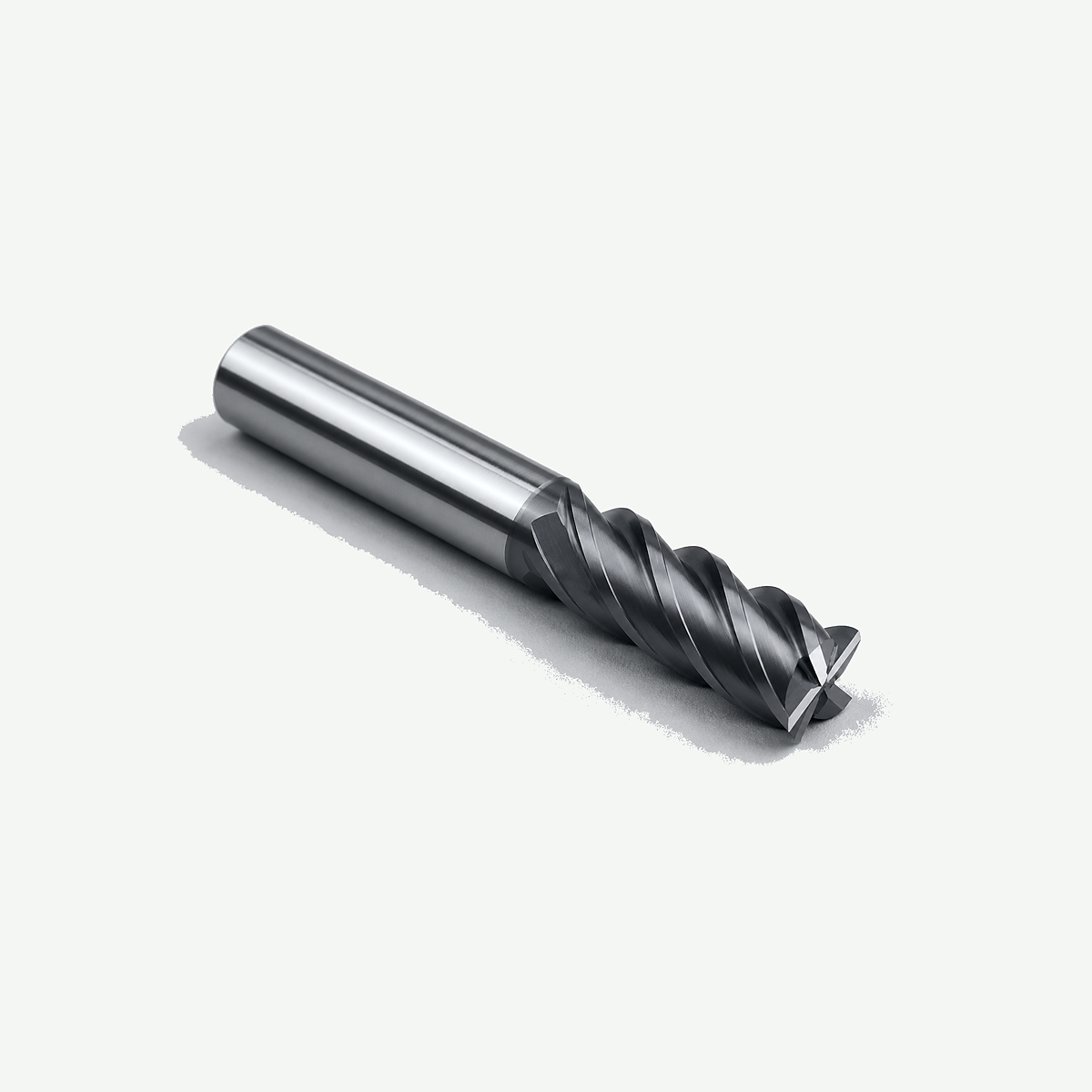
Start from the feature you must hold: square shoulder, contour, or a defined corner. Then check material family, usable stickout and how you will accept the first article. This family page routes you; child series pages hold geometry detail. HENTRY manufactures end mills to order under Guangdong Hentry Tool Technology Co., Ltd.
Primary geometries: square, ball nose, corner radius
These three solid carbide end mill geometries are peer starting points. Flute count and coating are attributes, not competing geometries.
Square / Flat End Mill
Sharp square shoulders, pocket walls and slotting where a true 90° corner is required in steel, stainless or cast iron.
Ball Nose End Mill
Spherical tip for 3D contours, blends and die/mold finishing where cusp height and effective diameter matter.
Corner Radius / Bull Nose
Defined corner radius when a sharp square corner chips or when the print calls a fillet at the floor.
Flute count and coating attributes
Choose these after the tip geometry. They refine chip space, finish and heat resistance; they do not replace square, ball or corner radius as the primary selection.
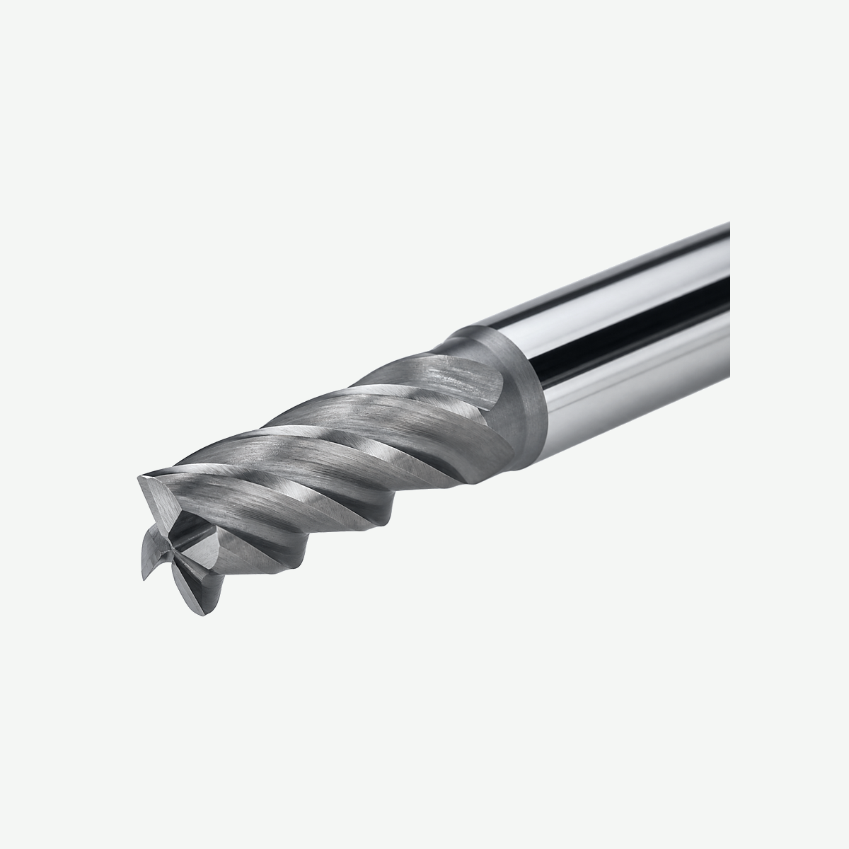
4-Flute Carbide End Mill
Flute-count path when finishing steel needs more edges in cut and chip volume still allows it.
Open 4-flute pathAlTiN Coated End Mill
Coating-family path when ferrous heat and abrasive wear drive the RFQ; other families are confirmed at drawing review.
Open AlTiN pathProcess series: high-feed and roughing
Dedicated stock-removal strategies. Use them when the process, not only the tip shape, defines the tool.
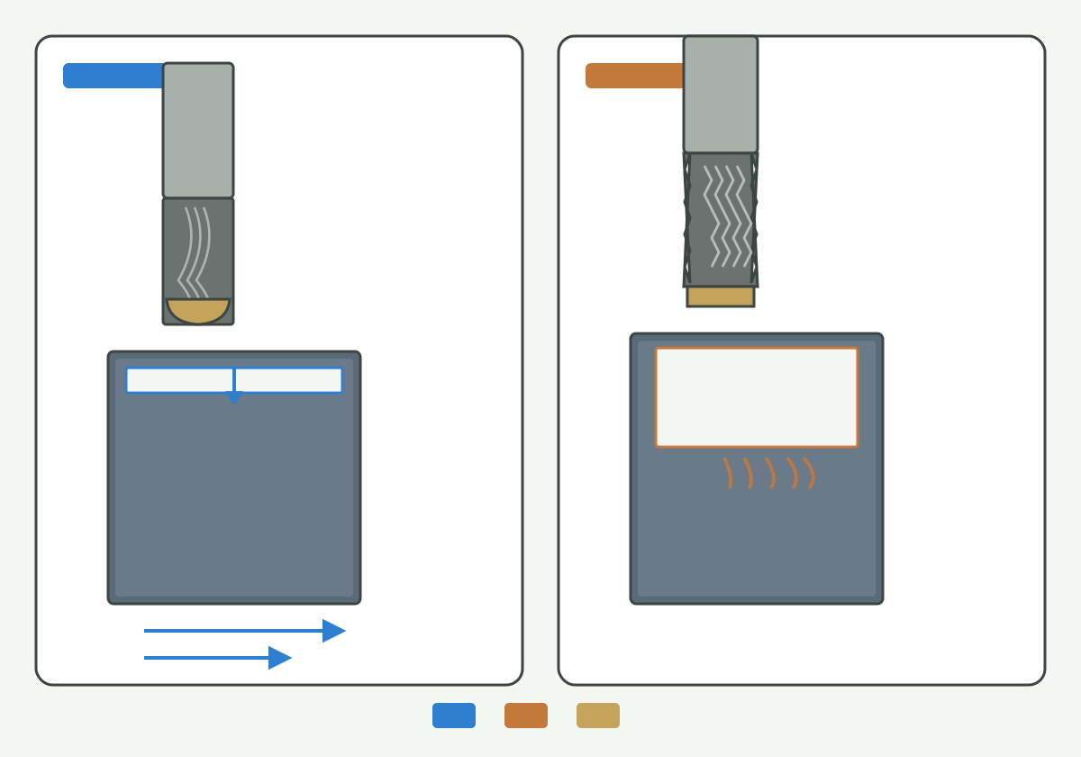
High-Feed End Mill
Shallow axial depth with high table feed for steel roughing when machine rigidity and toolpath support it.
Open high-feed seriesRoughing End Mill
Serrated / chipbreaker geometry for bulk removal before a finish pass with a square, ball or corner-radius tool.
Open roughing seriesAluminum and non-ferrous: carbide and PCD paths
Aluminum is not routed to PCD alone. Alloy grade, silicon content, duty cycle and finish target decide between a solid carbide aluminum end mill and a PCD milling cutter.
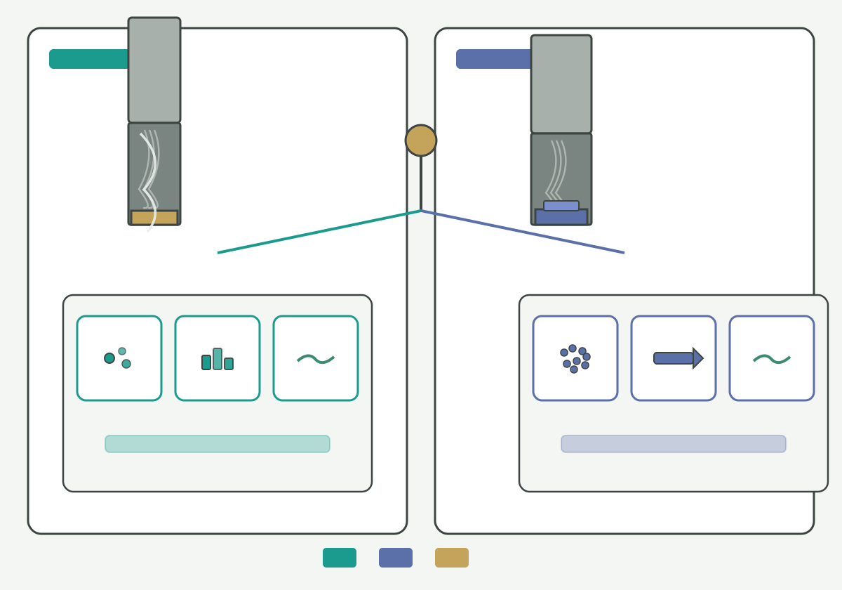
End Mills for Aluminum
Prefer when silicon is moderate, volumes are mixed, or geometry changes often and carbide polished flutes suit the duty.
Open carbide aluminum seriesPCD Milling Cutters
Prefer for high-silicon aluminum, long abrasive runs or when edge life and finish stability justify PCD after drawing review.
Open PCD milling seriesSend alloy designation, approximate Si%, feature class and annual volume so the path is confirmed against the part, not a material label alone.
Selection value (conditional)
These points describe what a correct geometry and reach decision can protect. They are not tool-life or percentage promises.
- Rigidity vs reach: shorter usable stickout usually improves wall accuracy when the fixture allows it.
- Corner integrity: a drawn corner radius often survives interrupted entry better than a sharp square corner in the same steel.
- Finish control: ball and corner-radius tools need an effective-diameter check so programmed feed matches the contact zone.
- Chip space: flute count must leave room for the chip the material actually forms; stainless and aluminum diverge here.
Specifications: series detail and to-your-drawing
Product specifications (PDF)
English milling catalogue V3.0 — series dimension tables for carbide end mills and related milling tools. This family hub does not invent public SKU rows; exact Ø / shank / flute length are confirmed to your drawing.
Engineering review: This family page is technically reviewed by Jiack Liu, Engineering Director, Guangdong Hentry Tool Technology Co., Ltd Review scope: primary geometry vs attribute vs process classification, aluminum dual-path framing, milling formula boundary, acceptance checklist for end mills. Review date: 2026-10. Next review trigger: new published series datasheet, change to geometry taxonomy, or update to a verified end-mill application record (see Application case).
This family page does not publish invented model codes or dimension tables. Geometry dimensions, flute length and shank options live on each series page and are confirmed to your drawing. Cutting diameter, shank diameter, flute length, overall length, flute count and end form are reviewed at RFQ; a series datasheet is available on request with your RFQ when Engineering has issued one for that series.
| What you need | Where it is handled |
|---|---|
| Tip geometry (square / ball / corner) | Primary geometry cards above, then the matching series page |
| Flute count or coating family | Attribute paths, confirmed at drawing review |
| High-feed or roughing strategy | Process series pages |
| Exact Ø, shank, flute length, stickout | RFQ / to-your-drawing; no public placeholder table |
| Approved Vc / fz for your part | Proposed after drawing and setup review — not listed as generic numbers here |
| Product specifications PDF | Download product specifications (PDF) above |
Materials and coatings check
Map the workpiece family to a series path first. Coatings are options inside a geometry, not a substitute for tip selection. Grain size, cobalt content, coating thickness and chemistry are not published here without a series datasheet.
| Workpiece family | Typical solid-carbide path | Notes |
|---|---|---|
| Steel (soft to pre-hardened) | Square, corner radius, high-feed, roughing | Coating often from the AlTiN / TiAlN family when heat and wear dominate |
| Stainless | Square or corner radius; flute count balanced for chip volume | Confirm coolant and stickout; work-hardening entry needs a stable hold |
| Cast iron | Square, corner radius or face-related tools when decks are wide | Abrasive wear may push coating choice at review |
| Aluminum & non-ferrous | Carbide aluminum EM and/or PCD milling | Decide from alloy / Si%, duty and finish — not an exclusive material tag |
Cutting data: general milling formulas only
The formulas below convert values you already chose. They do not supply an approved cutting speed (Vc) or feed per tooth (fz) for HENTRY end mills. Ball-nose and large corner-radius tools need an effective cutting diameter check at the programmed depth of cut.
vf (mm/min) = fz × n × zc
- n — spindle speed (rpm)
- Vc — cutting speed (m/min), chosen for material and tool, not taken from this page
- Dcap — effective cutting diameter (mm) at the relevant axial depth
- vf — table feed (mm/min)
- fz — feed per tooth (mm/tooth)
- zc — number of effective teeth in cut per the tool definition
Source definitions: Sandvik Coromant milling formulas and definitions. Process considerations: Sandvik Coromant milling knowledge.
Manufacturing and acceptance checks
Separate three records so a tool problem is not confused with a holder or workpiece problem.
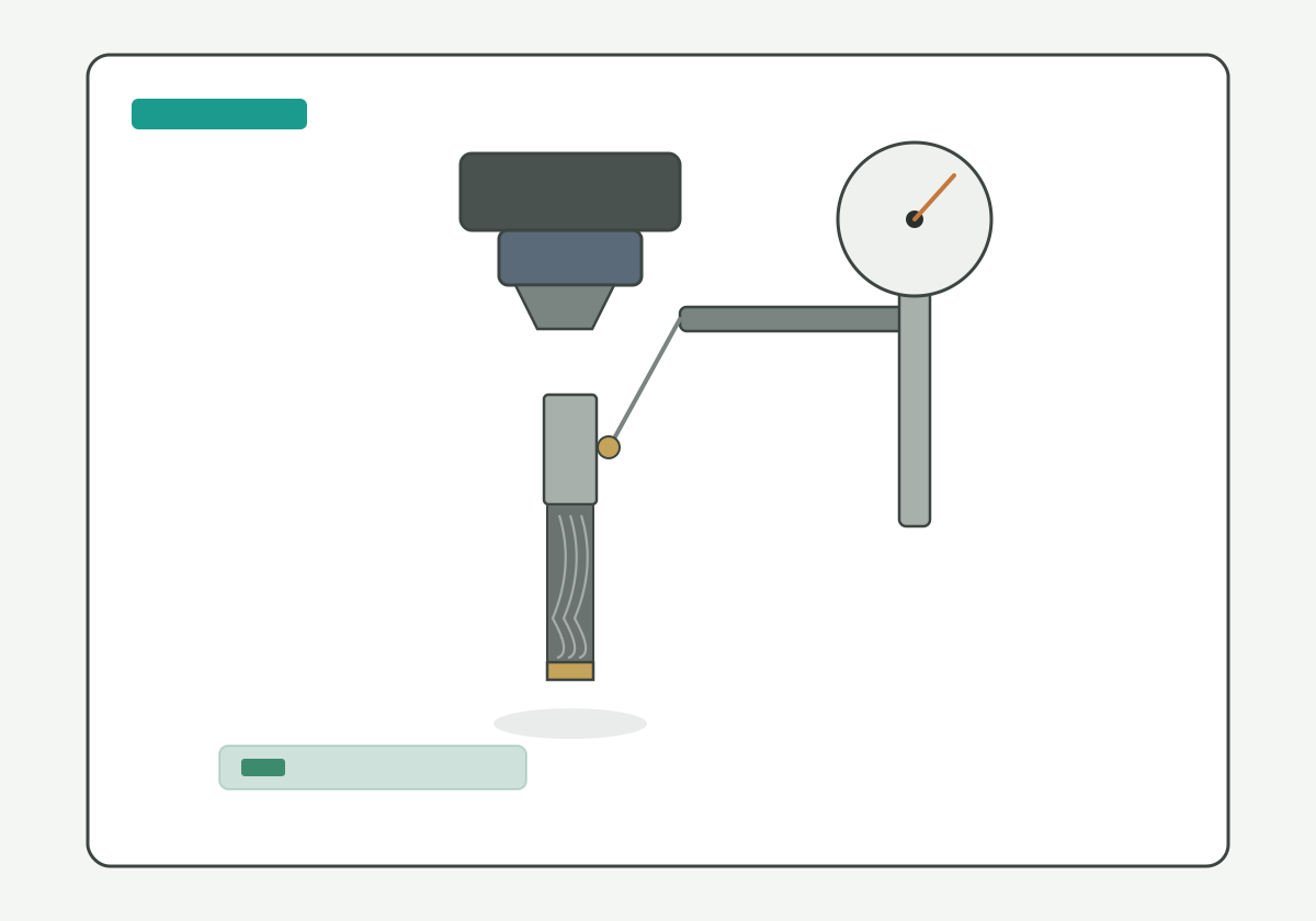
- Tool size and edge: cutting diameter, end form, corner radius or ball radius, edge preparation as agreed on the drawing.
- Holder runout: assembled runout and stickout in the holder that will run production; a stiff edge needs a stiff setup.
- First-article workpiece: wall, floor, blend or shoulder dimensions and surface requirements on the sample lot.
Factory context (CNC tool grinding including ANCA platforms used sitewide, presetter inspection) describes process capability in general. Equipment photographs are not an inspection report for a specific end mill design. Sample trials follow the sample validation process. Production tooling is made in HENTRY's own factory.
Milling diagnosis: symptom → check → action → verify
| Symptom | Check | Action | Verify |
|---|---|---|---|
| Corner chipping on square tools | Entry interruption, hardness, stickout, runout | Consider corner radius, shorter stickout or revised edge prep at review | First-article corner integrity and wall size |
| Chatter / poor wall | Holder type, stickout, radial engagement, flute count | Reduce engagement or stickout; revisit geometry vs high-feed strategy | Wall finish and dimensional band on trial lot |
| Short reach / deflection | Usable stickout vs required depth | Necked or longer-flute custom only after reach is justified | Depth and taper on sample walls |
| Built-up edge in aluminum | Alloy / Si%, polish, coolant, speed window | Compare carbide aluminum path vs PCD path | Surface and burr on first article |
| Rapid heat wear in steel | Vc input, coating family, dry vs wet | Confirm coating attribute path; do not invent Vc here | Flank condition on returned tools |
Application case: hard milling of an automotive mold cavity
Recorded customer-site trial. Results below were measured by the HENTRY engineering team at the customer site under the customer’s own tool-life criterion. They are not a transferable life guarantee for other parts, machines or setups.
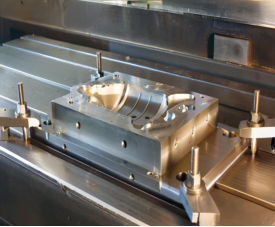
The part was an automotive-component mold in 42CrMo, machined on a vertical machining center with external coolant. The cutting tool was a Ø10 mm solid carbide end mill. The customer’s life requirement was to finish 6 post-heat-treatment molds + 6 pre-heat-treatment molds.
Process difficulties
- After quench, mold hardness typically reaches HRC48–62. The tip sees high squeeze and friction, so chipping and fast wear are common; heat concentrates at the tip and chips pack in closed cavities.
- The cavity is a continuous irregular 3D surface with ribs and depth transitions, so chatter, surface marks and corner overcut are hard to control.
- Quench distortion leaves uneven stock; load swings raise the risk of edge fracture and size drift.
- Tight GD&T on contours and holes means cutting force can deflect the tool or workpiece and shift the profile before die-cast product accuracy is checked.
Tool design applied on this trial
- Tip geometry: tip rake correction plus ultra-finish grind on top of standard grinding, to strengthen the tip, improve edge finish, reduce built-up edge and clear chips/heat faster.
- Rigidity / anti-chatter: unequal pitch, controlled length-to-diameter (stickout kept short), thicker core and a positive taper to raise overall stiffness.
- Substrate & coating: ultrafine-grain carbide for bend strength, toughness and resistance to plastic deformation; a high red-hardness, low-friction coating for wear and lubricity on hard mold steel.
Cutting parameters used
Ø10 mm · spindle speed n = 3500 r/min · feed rate vf = 2500 mm/min. Other main machining conditions were held equal versus the incumbent tool.
Result (customer life criterion)
Incumbent import brand: 6 post-HT + 4 pre-HT molds. HENTRY tool: 7 post-HT + 7 pre-HT molds — about 40% longer life under the same customer-site life criterion. Use this record for engineering discussion; re-validate on your machine, holder and print.
Custom end mills and RFQ checklist
When no series fits, or the print is ready to quote, use the custom end mill manufacturer path. Application records for specific end-mill jobs are available on request after drawing review; this page does not publish unverified case cards.
Send with the RFQ:
- Cutting diameter
- Shank diameter and shank style
- Flute length
- Usable stickout / reach
- End form: square, ball, corner radius (value), or special
- Flute count if known; coating preference if any
- Workpiece material / alloy (and Si% for aluminum)
- Feature class: shoulder, pocket, contour, face, thread-related
- Machine, holder, measured runout if available
- Acceptance / inspection requirements for tool and first article
- Drawing revision and file format
- Volume band; sample trial yes or no
Solid carbide end mill FAQ
How do I choose between square, ball nose and corner radius?
Match the tip to the feature: square for true 90° shoulders, ball nose for contours and blends, corner radius when the print calls a fillet or a sharp corner chips. Flute count and coating come after that choice.
Should aluminum go only to PCD?
No. Use the carbide aluminum series and the PCD milling series as parallel paths. Alloy, silicon content, duty cycle and finish target decide; send those with the drawing.
Why are 4-flute and AlTiN not listed as primary geometries?
They are attributes. The same square or corner-radius tool can be made with different flute counts or coatings; listing them as peer tip shapes mixes categories.
Do you publish cutting speeds and feeds on this page?
Only general milling formulas with units. Approved Vc and fz for your part are proposed after drawing and setup review, not as generic catalog numbers.
What if my drawing is already ready to quote?
Send it through the custom end mill manufacturer path or the RFQ form. Series cards here help when you are still choosing geometry.
Does HENTRY sell retail end mill kits?
No. HENTRY makes end mills to order and quotes each tool from your drawing and process data.
Technical references
- Sandvik Coromant — Milling formulas and definitions (speed, feed per tooth, table feed, effective diameter)
- Sandvik Coromant — Milling knowledge (feature, workpiece and machine considerations)
These sources support general milling relationships. They do not certify a HENTRY model, coating stack or case result.
Ready to select or quote?
Compare geometries above, or send the drawing with stickout and acceptance notes. Use the contact form on this page or the RFQ link.