
Product Detail
Solid Carbide Taps
Solid carbide taps selected by material, thread standard and hole type. Review geometry, tapping feed, inspection and drawing-based quotation requirements.
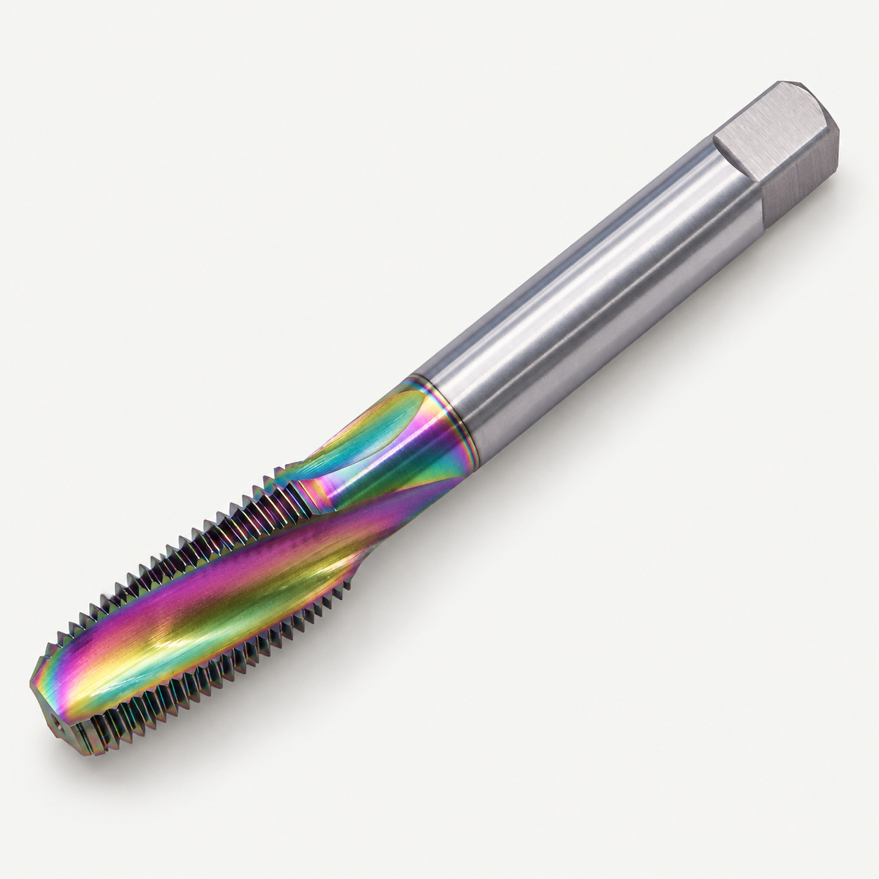
Choose the geometry for your hole, then confirm dimensions, material and tapping conditions.
Cutting and forming
Compare tap geometries
Match the process and chip route to your material, hole type and required depth. These reference-derived illustrations show the differences; final dimensions follow the selected tool drawing.
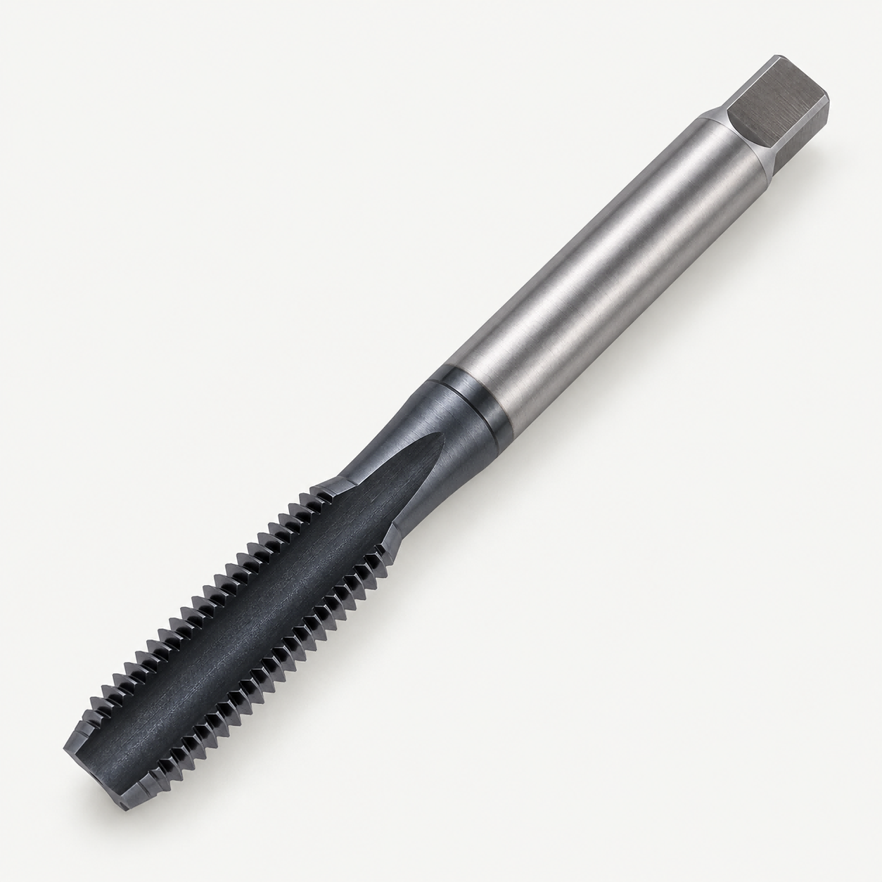
Spiral flute
A common route for blind holes with coiled chips; confirm helix, chamfer and bottom clearance.
Explore spiral flutes →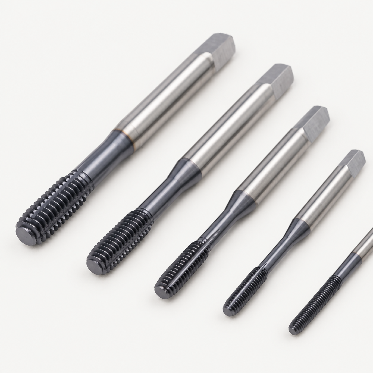
Forming tap
A separate chipless process. Confirm material formability, lubrication and the forming-specific pre-hole.
Explore forming taps →Illustrations do not certify carbide grade, coating chemistry or a particular model. For through holes with space for chips ahead of the tool, also compare spiral point taps; spiral point is distinct from plain straight flute. [1] [2]
Evaluate the complete process
When is solid carbide worth evaluating?
Wear-related changeovers
Assess carbide when wear limits a repeat operation. Compare accepted threads per tool under the same conditions.
Repeat production
Retain an identified tool, drawing and setup so that replacement proposals can be compared consistently.
Casting applications
Material-specific carbide designs exist for cast iron and non-ferrous castings. Match the actual grade; do not transfer another manufacturer's results. [6]
Coolant at the cut
Assess internal coolant where delivery and chip evacuation limit the process. Confirm the actual channel design and holder supply. [3] [7]
Controlled specification
Agree substrate, coating, chamfer and thread tolerance together; construction alone does not determine application fit.
Measured economics
Compare total cost per accepted thread, including inspection, downtime and rejects. A longer claimed life alone is not a purchase decision.
A benefit must be demonstrated on the application. Carbide does not correct an unsuitable pre-hole, misalignment or bottoming. [4]
Selected catalogue dimensions · mm
Representative solid carbide tap specifications
Compare eight catalogue configurations. SFT = spiral flute cutting; HT = straight flute cutting; NRT = forming. Confirm the exact model, application and current availability before ordering.
| Series | Model / EDP | Thread | OAL L | Thread length | Shank d | Chamfer |
|---|---|---|---|---|---|---|
| DIN-CB-SFT | WDS040070 | M4 × 0.7 | 63 | 13 | 4.5 | 2.5P |
| DIN-CB-SFT | WDS060100 | M6 × 1 | 80 | 17 | 6 | 2.5P |
| DIN-CB-SFT | WDS080125 | M8 × 1.25 | 90 | 16 | 8 | 2.5P |
| DIN-CB-SFT | WDS100150 | M10 × 1.5 | 100 | 18 | 10 | 2.5P |
| DIN-CB-HT | WDH060100 | M6 × 1 | 80 | 17 | 6 | 2.5P |
| DIN-CB-NRT | WDN06100B | M6 × 1 | 80 | 10 | 6 | 2P |
| DIN-CB-NRT | WDN08125B | M8 × 1.25 | 90 | 13 | 8 | 2P |
| DIN-CB-NRT | WDN10150B | M10 × 1.5 | 100 | 15 | 10 | 2P |
Source: Hentry English carbide tap catalogue, printed pages 13, 18 and 27. All eight entries list 6HX tap tolerance and DIN 371 dimensions. Thread length is the tool dimension, not the guaranteed full thread depth in a blind hole. P denotes thread pitch. Catalogue coating identifiers are YC-C50 for the illustrated SFT series and YC-T50 for HT; confirm the actual supplied coating. NRT is a separate forming process.
English PDF catalogue
Complete solid carbide tap specifications
Explore all catalogue series, dimension tables and technical reference charts. Includes Hentry company and contact details.
Download All Tap Specifications (PDF)English · 44 pages · 1.32 MB. Confirm the selected model, availability and application-specific cutting conditions before ordering.
Drawing-based specification
Specify the tap before comparing offers
Use the complete workpiece thread callout and tool dimensions. The table below is a quotation checklist, not a published stock-size range.
| Field | Include in your enquiry | Confirm in the proposal |
|---|---|---|
| Thread | Standard, size, pitch or TPI, hand and tolerance class | Matching thread profile and tap tolerance; allowance for any later treatment. |
| Hole | Blind/through, pre-hole diameter and tolerance, full thread depth and drilled depth | Chamfer, tool-tip clearance and thread-forming reach. |
| Tool dimensions | Overall length, threaded length, neck/reach, shank and square where required | Dimensions and symbols on the approved tool drawing. |
| Machine interface | Holder, clamping length, projection and dimensional standard | Compatible shank/square; DIN, ISO, ANSI or JIS reference as specified. |
| Supply | Drawing revision, quantity, existing model and replacement priorities | Tool identification, agreed inspection scope and change control. |
Thread standards and tap dimensional standards describe different requirements. A shank standard is not the finished-thread tolerance. [5]
Blind-hole clearance: three depths to keep separate
Full thread depth is the length of complete thread required by the part. The tapping position must account for the tool's cutting chamfer and tip. Drilled depth must also leave clearance for the drill-point shape and the agreed chip space. Establish these from the actual tool and hole drawings. [2] [3]
Workpiece, substrate & coating
Match the tool specification to the material
| Workpiece | Selection focus | Information to supply |
|---|---|---|
| Gray/ductile cast iron | Grade-specific cutting edge, chip space and wear behavior | Exact grade, hardness, casting skin and interrupted features. |
| Aluminum/non-ferrous castings | Adhesion, abrasive constituents and chip removal | Alloy, condition, silicon content where relevant and coolant route. |
| Steel/stainless steel | Do not assume the same geometry or carbide grade as for cast iron | Alloy, heat treatment, hardness, chip behavior and pre-hole quality. |
| Hardened steel/titanium/high-temperature alloys | Tool-specific feasibility review | Exact grade and condition; a carbide label alone is not a hardness or material approval. |
Casting routes are supported by manufacturer-specific examples [6] [7]. They do not establish an HC material range.
Agree substrate, coating and edge preparation separately
Request the selected carbide grade, edge preparation and coated or uncoated condition. If the application requires controlled WC grain size, cobalt content, coating chemistry or thickness, record those requirements against the tool identification.
Coating is an application choice, not an automatic consequence of carbide construction. An uncoated carbide configuration is illustrated by the Gühring reference [7]; its specification is not an HC coating recommendation.
Pitch-synchronous tapping
Calculate feed from pitch, not flute count
Spindle speed conversion
n = 1000 × Vc / (π × D)
n in rpm; Vc in m/min; D is the applicable tap cutting diameter in mm. Select Vc for the actual tool and material first. [9]
Single-start synchronous feed
F = n × P
F in mm/min; P is pitch in mm. For inch TPI in a metric program: F = n × 25.4 / TPI. [8]
Conversion relationships, not HC starting settings. The Haas reference is a 2016 programming document; confirm units, feed mode, cycle and synchronization in the current manual for your machine and holder. Floating attachments require their own setup instructions. [8]
What changes the starting cutting data?
Identify the tool code, material and hardness, thread engagement, pre-hole condition, holder, projection and coolant delivery. Confirm cutting speed, synchronized feed, reversal and approach/retract behavior before a trial. Do not use milling feed-per-tooth calculations or alter tapping feed independently of synchronization. [3] [8]
Pre-hole and coolant checks before the first cut
Measure the prepared hole and inspect its surface; drilling damage can affect tapping. Match lubrication and coolant delivery to the cut, with a clear chip-removal route. A forming-tap pre-hole is not a cutting-tap drill size. [2] [3]
Pre-hole sizes and synchronized feed examples
Choose the cutting or forming process before setting the pre-hole. The catalogue gives the following metric examples; forming values are the JIS class 2 reference column and depend on the specified tap limit and thread engagement.
| Thread | Cutting: nominal pre-hole Ø mm | Forming: reference pre-hole Ø mm | Feed at an illustrative 1,000 rpm, mm/min |
|---|---|---|---|
| M4 × 0.7 | 3.3 | 3.65–3.70 | 700 |
| M5 × 0.8 | 4.2 | 4.59–4.66 | 800 |
| M6 × 1 | 5.0 | 5.48–5.57 | 1,000 |
| M8 × 1.25 | 6.8 | 7.34–7.41 | 1,250 |
| M10 × 1.5 | 8.5 | 9.18–9.28 | 1,500 |
Pre-hole source: catalogue printed pages 32 and 34. These are process-specific references, not interchangeable drill sizes or a tolerance release for every material. Verify actual hole diameter, material condition, required thread fit and the selected tool proposal. Feed values are calculated as F = n × P for single-start synchronous tapping; 1,000 rpm is a calculation example, not a recommended spindle speed. [8]
Speed-to-feed example
For M6 × 1, an assumed Vc of 10 m/min gives n ≈ 531 rpm and F ≈ 531 mm/min. This illustrates the conversion only; it does not establish a cutting speed for a material or tap series. [8] [9]
Confirm before the trial
Agree Vc against the exact series, coating, material and hardness. Then set pitch-synchronous feed, coolant delivery, usable thread depth, approach, reversal and bottom clearance for the actual machine and holder.
The catalogue speed table lists other series codes without a confirmed mapping to the CB solid carbide taps above. Its ranges are therefore not presented here as CB-series starting settings.
Tool + setup + finished thread
Agree acceptance before production
| Check | Define the method | Record |
|---|---|---|
| Tool geometry | Drawing dimensions, profile, chamfer and edge condition | Results tied to tool identification and drawing revision. |
| Mounted setup | Holder seating, projection, alignment and applicable runout check | Measurement position and setup-specific result. |
| Prepared hole | Diameter, depth and surface condition against the process plan | Actual hole results before attributing a defect to the tap. |
| Finished thread | Specified GO/NO-GO gauging and additional drawing-required checks | Gauge identity, required depth, sampling and any finish result. |
Tap tolerance and finished-thread acceptance are related but distinct. [5] Review manufacturing and quality →
Symptom → check → validate
Solve the cause before changing the tool
Chipping or breakage
Possible causes: Possible causes include trapped chips, inadequate lubrication or bottoming.
Review: Check the pre-hole, clearance, holder and wear first; then review the tool-specific settings.
Validate: Record the failed edge, hole condition and stage of failure. [4]
Thread fails GO/NO-GO checks
Possible causes: Possible causes include tap tolerance, wear, axial-feed errors or a pre-hole problem.
Review: Check the gauge, actual thread requirement and setup before changing tool tolerance.
Validate: Log results against tool identity and hole depth. [4]
Rapid wear or built-up edge
Possible causes: Possible causes include a mismatched edge/surface treatment or lubrication.
Review: Inspect the wear pattern and material condition; compare a matched tool proposal.
Validate: Compare accepted threads and edge condition at agreed intervals. [4]
Poor finish or rising torque
Possible causes: Inspect chip accumulation, pre-hole condition, wear and lubricant delivery.
Review: Review those observations before changing speed; preserve pitch synchronization.
Validate: Record machine load where meaningful and confirm thread acceptance. [4]
Hentry reported application
M8 blind-hole tapping in an automotive turbine housing
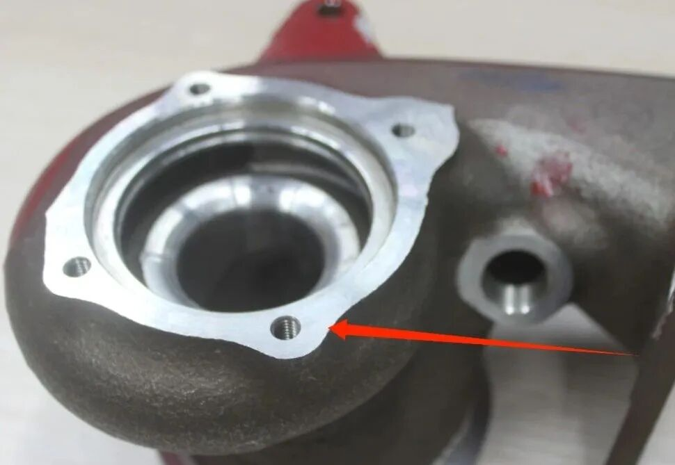
HC solid carbide small-helix spiral flute tap for blind-hole threading in a 1.4837 automotive turbine housing.
- Material / hardness
- 1.4837 / HB 200–240
- Machine / interface
- Doosan vertical machining centre / BT50
- Coolant / hole
- External coolant / blind hole
- Thread / chamfer
- M8 × 1.25 / 1.5–2 pitches
- Program / depth
- N = 200; F = 250; one pass / 21 mm cutting depth
Result applies to the reported setup. No comparator or wear endpoint was supplied; no improvement percentage is claimed.
Parameter interpretation and case scope
N = 200 rpm and F = 250 mm/min are consistent with single-start M8 × 1.25 tapping (200 × 1.25 = 250). This interpretation follows the N/F notation and pitch relationship; confirm the original machine program before reuse. The stated 21 mm is cutting depth, not verified full-thread depth.
Source: customer application summary supplied to HC. Solid carbide construction was confirmed by HC. Exact catalogue series, coating and original inspection records are not provided. The recorded result is not a performance claim for every CB-series tap; validate other applications.
Application trial
Build a repeatable validation record
01 / Define the baseline
Record material, thread, prepared hole, existing tool, setup and the acceptance criteria.
02 / Run the agreed setup
Retain the tool identity, program revision, holder, coolant and actual cutting conditions.
03 / Compare accepted output
Measure thread acceptance, cycle time, tool changes and rejects over an identified batch.
This is a validation plan, not a customer test result. Review the sample validation process →
Before you order
Solid carbide tap questions
Are solid carbide taps suitable for every hardened steel?
No. Send the steel grade, heat-treatment condition and measured hardness. Carbide construction alone does not establish a 50 HRC or 60 HRC working range.
Which tap geometry should I use for a blind hole?
Assess the material, chip behavior, usable thread depth and bottom clearance together. A spiral flute is a common blind-hole route, but the actual carbide geometry and chamfer need application confirmation.
Is DIN 371 or DIN 376 the finished-thread standard?
No. A tap dimensional standard does not replace the workpiece thread callout and tolerance. Specify both the thread requirement and the required shank, square and overall length.
Can I use a forming-tap pre-hole for a cutting tap?
No. Cutting and forming have different pre-hole requirements. Confirm the process-specific hole diameter and tolerance before machining.
How is tapping feed different from milling feed?
In synchronous single-start tapping, axial advance per spindle revolution follows the thread pitch. Do not multiply the feed by flute count or use a milling feed-per-tooth calculation.
What do you need for a quotation?
Send the complete thread designation and tolerance, material and hardness, hole type, full thread depth, drilled depth, quantity and drawing. Add machine, holder, coolant and any existing tool identification.
Technical basis
Technical references
9 sources. Expand a row for scope; competitor data are not HC specifications.
OSG — Tap families
Hole-type and cutting/forming distinctions; general guidance.Sandvik — Tap and chamfer selection
Geometry and chamfer principles; not HC catalogue dimensions.Sandvik — Tapping operation tips
Pre-hole, clamping and coolant checks; system-specific values are not transferred.Sandvik — Tapping troubleshooting
Diagnostic causes for size errors, wear, chipping and breakage.Sandvik — Standards and tolerances
Thread fit, shank and dimensional-standard distinctions.OSG — Carbide tap application example
Manufacturer-specific carbide designs for casting applications; not HC performance evidence.Gühring — Carbide configuration example
An uncoated, radial-coolant carbide design; its dimensions and ratings belong to Gühring.Haas — Tapping feed relationships
2016 document: feed, pitch and unit relationships only; use the current manual for your control.Sandvik — Speed formulas
Metric cutting-speed/RPM relationship; milling chip-load formulas do not apply to synchronous tapping.
All tap series · Brazed carbide construction · Compare thread milling
Solid carbide tap enquiry
Request a tap proposal
Send the thread, material, hole depths and quantity. Attach a drawing or existing tool details.