
Product Detail
Custom PCD Combination Drill-Reamers
Custom combination drill-reamers integrate drilling, semi-finishing, precision reaming and selected multi-diameter features for automotive aluminum and precision-hole production—drawing review, sample validation and RFQ.
Drawing-Based Custom PCD Tooling
One Tool Path. Multiple Precision Operations.
Combine drilling, semi-finishing, precision reaming, chamfering, counterboring and selected multi-diameter features in one rigid tool body—engineered around your component drawing, machine interface and production target.
Designed from the finished feature
Selected by material and cutting function
Drawing, sample and revision control

What Is a PCD Combination Drill-Reamer?
Unlike a general-purpose combination reamer selected only by nominal diameter, a production PCD drill-reamer is developed from the finished component feature. Hole depth, tolerance, surface requirement, datum relationships, material, coolant route, machine interface, holder, overhang and annual volume all influence the final structure.
Why custom and combination tools sit in the product-mix shift is covered under cutting-tool product-mix and custom tools in the industry outlook.
The objective is not simply to place more cutting edges on one body. The objective is to control the complete machining sequence so that each cutting section receives an appropriate stock allowance, chip space, coolant supply and level of support. This is why HENTRY begins with the component drawing and current process rather than a fixed catalogue geometry.
A combination concept may reduce tool changes, offsets, holders and magazine positions. It may also help maintain axial relationships between related features. However, integration is not automatically the best choice for every job. Deep blind holes, high chip volume, incompatible cutting conditions, weak rigidity or frequently changing components may be better served by separate tools. HENTRY evaluates both routes before the design is fixed.
For a single finished-bore operation, compare our custom PCD reamers. For broader non-standard projects, review custom cutting tool engineering.
CONVERSION OUTCOMES
Name the Operation: Step Drill vs Drill-Reamer vs Combination Reamer
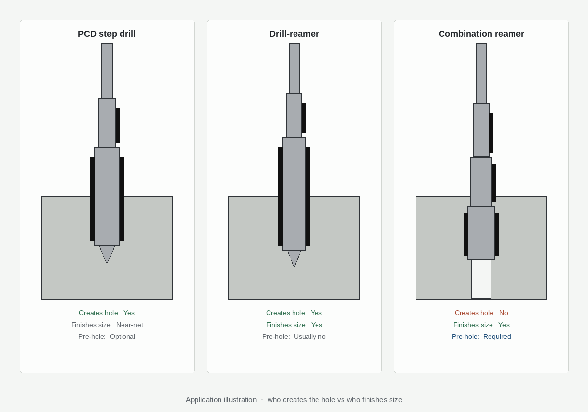
Shops often call any multi-diameter tool a “combo.” When the drawing shows a drilled step, a finished diameter and a chamfer, that loose name can put the wrong tool family on the RFQ.
This table names who creates the hole and who owns final size. It does not decide whether to integrate or stay split—that walk stays on the drill-then-ream vs combination decision tree. And it does not promise that one body always deletes a station.
| Name | Creates hole? | Finishes size? | Pre-hole? | Typical watch-outs |
|---|---|---|---|---|
| PCD step drill | Often yes | Steps can be near-net | Depends on the design | A tight finish band may still need a separate reamer after the steps are created |
| Drill-reamer / combo drill-ream | Yes | Finish section owns the critical Ø | Usually no | Chip space and deep-blind packing at the finish edges — deep-blind risks |
| Combination reamer (multi-feature finish) | No / weak | Multi-step or contour finish | Needs a prepared hole | Not a create tool; divide the job with step/form RFQ and the PCD reamer structure |
If the drawing is mainly create multi-diameter in a carbide-friendly route, start at step carbide drill vs PCD combination—that page owns the family split. This H2 only stops the name mix-up on the combination product.
How to read the print before you name the tool
Mark each feature on the drawing:
- Create — the section that must open material (point, first Ø, stock removal).
- Finish — the section that must hold the accepted size/finish band.
- Related form — chamfer, counterbore, step length, or contour that must stay on the same axis.
If create and finish both sit on one body, you are talking about a drill-reamer (this product family). If finish-only features stack on a prepared hole, you are talking about a combination reamer or a step/form reamer—not a pierce tool. If the steps only have to exist, and the finish band is still open, you may be talking about a step drill.
HENTRY reads the drawing, names those features in writing, and freezes sample acceptance before the body is locked. That is the service loop—not a slogan about fewer tools.
What this page will not decide
- Whether chip, parameter, position, or volume nodes allow integration — decision tree.
- Whether a deep blind bottom will pack chips against the finish edges — deep-blind risks.
- Per-step Ø / length / R fields for a finish form tool — PCD step and form reamer RFQ.
Send the print with the features named (or circled). HENTRY returns the name it will quote, the sample-acceptance list, and the RFQ pack: PCD Reamer RFQ Checklist → Custom Cutting Tool RFQ. First-article still follows sample validation.
---
Why Shops Evaluate a Combination Drill-Reamer
- Fewer tool changes — pierce and finish in one programmed path when the feature set allows.
- Cycle-time pressure — remove a separate reamer station when chip and coolant conditions support it.
- Lower stack-up error — coaxial drill/ream diameters share one referenced tool body.
- Multi-step features — rough + finish + chamfer (or steps) on one body when print notes agree.
- Custom from print — diameters, lengths and coolant outlets follow the component drawing, not a catalog compromise.
Combination is not always right. Read when a PCD combination drill-reamer is the wrong choice and the drill-then-ream vs combination decision tree. Deep blind limits: deep-blind PCD combination risks.
Multiple Holemaking Operations. One Controlled Tool Path.
A conventional route can require one tool to drill, another to semi-finish or bore, another to ream and another to chamfer. Every additional operation introduces tool-change time, a holder and preset requirement, an offset, a magazine position and another relationship that must be controlled across production shifts.
| Separate process | Integrated drill-reamer concept |
|---|---|
| Drill the initial hole | Drill or prepare the hole with the front section |
| Retract and change tool | Continue through the engineered cutting sequence |
| Semi-finish, bore or correct stock | Control intermediate allowance on the same body where appropriate |
| Change tool and precision ream | Finish the critical diameter with selected PCD edges |
| Change tool and chamfer | Generate an approved chamfer, counterbore or face where feasible |
| Inspect relationships between operations | Validate the integrated feature against one approved tool revision |
Potential savings come from reduced non-cutting activity and process simplification—not from an assumed universal percentage. The real cycle-time and cost effect should be calculated from the existing route, tool-change time, inspection burden, annual volume and sample results.

Integrated Cutting Sequence
Three Features. One Referenced Tool Body.
The cutting sections are engineered as one system so related hole features can be produced from a common tool axis. The final geometry depends on the component drawing, stock condition and available chip space.
Configure the Tool Around the Finished Feature
Pilot Drilling
The front section establishes or enlarges the initial hole. Point geometry, flute form, margin design and chip space are selected for the material, depth and entry condition.
Semi-Finishing
A controlled intermediate allowance can help the final PCD edge work consistently. The semi-finishing section is designed together with the finishing section, not as an isolated feature.
Precision Reaming
PCD cutting edges finish the critical diameter and surface. Edge count, cutting width, back taper, rake, relief and optional support features are application-specific.
Chamfering
Entry or exit chamfers can be integrated when the axial position, cutting direction and chip path allow a stable sequence without creating a fragile edge.
Counterboring & Spot Facing
Selected counterbores and faces can share the body when the feature stack, access and cutting parameters remain compatible.
Stepped Diameters
Multiple related diameters can be integrated where flute space, tool stiffness, datum strategy and inspection method are clearly defined.
When Does a Combination Tool Make Sense?
| Good fit signals | Reasons to consider separate tools |
|---|---|
| Stable, repeat production with meaningful annual volume | Frequent component changes or very short batches |
| Related hole features can share one datum and tool path | Drilling and finishing require incompatible speeds or feeds |
| Machine, holder and fixture provide adequate rigidity | Weak rigidity, excessive overhang or unresolved runout |
| Internal coolant or directed external coolant can support chip evacuation | Deep blind holes with limited chip space or cross-hole interruption |
| The combined route removes tool calls, offsets or inspection complexity | The integrated body would become inaccessible, fragile or difficult to inspect |
A normal review follows the conditions in the existing process. If the part would be safer with a universal correction operation or an independently adjustable finishing step, HENTRY will recommend a separated concept before quotation.
Select the Cutting Material by Workpiece and Operation
PCD is highly wear resistant and can maintain a sharp edge in suitable non-ferrous and abrasive materials. It is not the default choice for every metal. The drilling and finishing sections may use different cutting materials where process freedom and chip control require it.
| Workpiece / condition | Typical design direction |
|---|---|
| 6061, 6082 and other wrought aluminum | PCD finishing edges with a compatible carbide or PCD drilling section |
| ADC12, A380 and high-silicon die-cast aluminum | Wear-resistant PCD selection, polished chip-contact areas and directed coolant |
| Copper and brass | Application-specific geometry for burr control and surface quality |
| CFRP or abrasive composites | Dedicated edge design based on laminate, entry/exit and damage limits |
| Steel and stainless steel | Usually reviewed as a solid-carbide drilling application rather than conventional PCD finishing |
See our high-silicon aluminum machining guidance and solid carbide drills for steel and stainless steel.

Engineering Inputs That Define the Tool
A reliable concept requires more than a tool name and final diameter. The following information allows HENTRY to evaluate the tool concept, manufacturing route, validation scope and commercial risk.
Component & Feature
- Component drawing with datums, depths, steps and chamfers
- Finished diameter, tolerance, surface finish and GD&T
- Through or blind hole, interrupted cuts and cross holes
- Incoming hole condition and stock allowance
Material & Volume
- Material grade, silicon content and heat condition
- Casting skin, inclusions or abrasive reinforcement
- Annual volume, batch size and shift pattern
- Current tool life and reason for replacement
Machine & Process
- Machine type, spindle, interface, holder and overhang
- Coolant route, pressure, flow and filtration
- Current speed, feed, cycle and chip problem
- Inspection method and acceptance expectation
Use the Custom Cutting Tool RFQ Checklist to prepare the drawing and application details.
Stability Depends on More Than the PCD Edge
Chip evacuation through blind and cross holes
A through hole may allow chips to leave in the feed direction, while a blind hole must return chips through the available flute space. If chips collect around a following reaming edge, they can be recut, dragged across the bore or packed near the bottom. Cross holes and interrupted features can change chip formation and cutting-edge loading. The flute volume, coolant exit, drilling sequence and programmed motion must therefore be designed together.
Internal coolant and MQL
Internal coolant holes can be directed toward drilling and finishing zones to control temperature, reduce adhesion and move chips away from the finished surface. Pressure alone does not define success; flow, outlet position, chip size, hole depth, filtration and the available exit path also matter. If MQL is required, lubricant delivery and chip transport must be evaluated from the machine system. What changes on the tool itself for MQL is covered in MQL drilling and reaming tool requirements.
Rigidity, holder and runout
A long multi-stage tool creates bending and torsional loads. Body diameter, overhang, connection style, holder condition, spindle interface and fixture stiffness influence cutting stability. Tool runout should be checked at the specified inspection position and interpreted with the holder and spindle. If the machine interface is the limiting factor, adding another cutting section will not solve the root cause.
Reaming allowance and entry condition
Too little effective allowance can lead to rubbing or inconsistent cutting; too much can overload the finishing edge and disturb chip evacuation. Incoming hole diameter, straightness, position and condition should be established during application review. HENTRY does not apply one universal allowance to every diameter, material and geometry.

Define Acceptance Before the Tool Is Released
“High precision” is not a sufficient acceptance criterion. A custom program should distinguish what is inspected on the tool from what is validated on the customer’s complete production process.
| Tool release check | Purpose |
|---|---|
| Approved tool drawing and revision | Fix the component-derived geometry and inspection method |
| Critical cutting diameters and step lengths | Verify the tool against drawing requirements |
| PCD edge condition and cutting geometry | Confirm edge preparation and freedom from visible defects |
| Runout at the agreed inspection position | Provide a controlled tool-level measurement |
| Internal coolant route and continuity | Verify the designed flow path |
| Tool identification and revision record | Support repeat orders and change control |
Production capability still depends on machine, holder, fixture, coolant, workpiece variation, programmed parameters and measurement system. Acceptance values should therefore be stated at the correct level. See Manufacturing & Quality Evidence and the Sample Validation Process.
Typical Automotive and Precision-Hole Applications
Hydraulic & Valve Bodies
Stepped bores, intersecting ports and sealing features require controlled burrs, surface condition and related diameters. A custom tool may combine pilot drilling, finishing and entry chamfer where chip paths and cross holes are manageable.
Transmission & Fluid-Control Housings
Aluminum housings often contain bearing, valve or fluid-control features with related diameters and axial steps. Integrating compatible operations can reduce tool calls while the validation plan focuses on feature relationships, bore quality and stability.
EV Motor Housings
Bearing seats, mounting features and lightweight aluminum structures place demands on alignment, burr control and thin-wall stability. Tool mass, cutting forces, coolant and fixture support must be evaluated with the housing.
Cylinder Heads & Blocks
Guide bores, cap-plug features and related steps may benefit from monobloc or guided concepts. Water passages, cross holes and internal cavities require special attention to chip control inside the component.
Compressor Components
Precision housings, manifolds and similar components can include deep or intersecting bores. A combination tool is evaluated against the same principles: compatible cutting conditions, rigid support, a practical chip route and measurable acceptance criteria.
Steering & Brake Components
High-volume safety-related components need stable feature relationships, controlled edges and repeatable inspection. Anonymized project data and sample evidence can be used where confidentiality limits public disclosure.

Application Fit
Designed Around Related Features in Aluminum Housings
Combination tooling is most valuable when drilling, finishing and chamfering features share a controlled relationship and the production environment can support stable chip evacuation.
Application Review — 6061 Aluminum Brake Valve Body
Anonymized Combination-Tool Concept
A customer machining an aluminum brake valve-body required multiple related diameters. Separate drilling and finishing operations added tool changes and created more relationships to manage between the initial hole and the finished feature. The engineering review focused on the complete component drawing, material, incoming hole, current route, holder, coolant, cross-hole geometry and inspection plan.
HENTRY developed a custom PCD combination concept around the finished part feature. The cutting sections were arranged to integrate compatible operations on one body while the drilling section and chip-control details were defined from the actual stock and coolant path. The concept was not treated as a universal catalogue tool.
Validation focus
- Finished bore size and related feature dimensions
- Surface finish and visible bore condition
- Burrs at entries, exits and intersecting features
- PCD edge wear and chip-contact evidence
- Cycle stability over the agreed sample
- Feedback recorded against the approved tool revision
From Drawing Review to Repeat Supply
- Application review: Confirm the component drawing, material, incoming feature, current route, machine, holder, coolant and inspection method.
- Concept review: Compare an integrated concept with separate-tool alternatives and identify technical risks.
- Drawing confirmation: Define cutting sections, coolant route, interface, critical dimensions, inspection points and tool revision.
- Manufacturing and inspection: Produce the body and PCD edges, inspect agreed characteristics and trace the release record.
- Sample validation: Evaluate the finished part, wear pattern, burr condition and cycle stability under the agreed production conditions.
- Revision and repeat supply: Record approved changes, freeze the validated specification and plan reconditioning or repeat orders.
Regrinding or retipping feasibility depends on the tool structure, remaining PCD, edge damage, dimensional restoration and approved revision. Reconditioned tools should be returned to a controlled drawing and inspection basis rather than treated as an informal repair.
Compare Cost per Acceptable Part—not Tool Price Alone
A custom PCD combination tool normally has a higher acquisition cost than a standard drill or reamer. The commercial decision should compare the total process cost and the number of acceptable parts produced, not the price of one tool in isolation.
Process time
Count tool changes, non-cutting moves, offset adjustment, tool setting and inspection interruptions.
Quality burden
Include scrap, rework, bore inspection, burr removal and the risk of feature relationships drifting between operations.
Tool lifecycle
Include initial tool cost, validated life, regrind or retip potential, logistics, spare-tool policy and repeat-order control.
Custom Combination Tools for Distributors and OEM Programs
HENTRY supports distributors that own the local customer relationship and need factory engineering behind a non-standard project. Support can include application-data review, customer-specific quotations, sample planning, drawing-revision control, repeat-order identification and a defined private-label scope.
OEM and private-label programs can define geometry, product identification, packaging, documentation and inspection scope project by project. The approved tool drawing and revision remain the technical basis for repeat supply, brand protection and replacement-tool traceability.
Learn about the HENTRY Distributor Program, OEM/ODM Cutting Tool Manufacturing and Private-Label Cutting Tools.

Frequently Asked Questions
What is a PCD combination drill-reamer?
It is a custom rotary tool that combines drilling or hole preparation with precision finishing operations such as reaming, chamfering, counterboring or selected stepped diameters. The design is based on the component drawing, material and production process.
Which operations can be integrated into one tool?
Pilot drilling, semi-finishing, precision reaming, chamfering, counterboring, spot facing and selected multi-diameter features may be combined when the axial stack, chip route, cutting conditions and tool stiffness are compatible.
Which materials are suitable for a PCD drill-reamer?
PCD is normally considered for aluminum, high-silicon aluminum, copper alloys and selected abrasive non-ferrous or composite materials. Steel and stainless-steel holemaking is usually evaluated with solid carbide rather than conventional PCD cutting edges.
Can the drilling and reaming sections use different cutting materials?
Yes. A hybrid concept can use carbide for one function and PCD for another when this improves geometry freedom, chip control, manufacturability or cost. The transition between sections still has to be reviewed as one system.
When are separate tools the better choice?
Separate tools may be better for short runs, frequently changing parts, very deep blind holes, incompatible drilling and finishing parameters, weak rigidity, unresolved chip evacuation or processes that need an intermediate positional correction.
How is internal coolant designed?
Coolant outlets are directed toward the cutting zones that need cooling, lubrication or chip transport. Pressure, flow, filtration, hole depth, chip size and exit path are reviewed together; pressure alone does not guarantee successful chip evacuation.
What information is required for a quotation?
Provide the component drawing, material, annual volume, current process, machine, holder, coolant condition, finished-hole requirements, inspection method and any known chip, burr, wear or stability problem.
How is a custom tool validated?
The validation plan should connect the approved tool drawing to finished-part dimensions, surface condition, burrs, chip behavior, edge wear and cycle stability under agreed production conditions. Results and changes are recorded against the tool revision.
Can a combination drill-reamer be reconditioned?
Reconditioning depends on the remaining PCD, edge damage, tool structure, dimensional restoration and approved revision. HENTRY reviews regrind or retip feasibility rather than promising a universal number of cycles.
How should buyers compare tool economics?
Compare cost per acceptable part, including tool changes, setting, inspection, downtime, scrap and reconditioning—not only initial tool price. Any claimed improvement should state the process baseline and validation conditions. A broader estimation and cycle-time framework is in the CNC machining cost guide.
PCD or carbide for a combination drill-reamer?
PCD combination tools fit abrasive non-ferrous and high-volume aluminum when both pierce and finish edges stay in the PCD window. Carbide (or mixed constructions) may fit ferrous work, lower volume, or when drilling and reaming duty cycles differ. HENTRY reviews material and feature stack before recommending one body or a split process.
What's the difference between a PCD step drill, a drill-reamer, and a combination reamer?
A PCD step drill mainly creates stepped or related diameters; the steps can be near-net, but a tight finish band may still need a reamer. A drill-reamer (this product) creates the hole and lets the finish section own the critical Ø in one tool path—usually without a separate pre-hole. A combination reamer is a multi-feature finish tool: it needs a prepared hole and should not be RFQ’d as a pierce tool. Unsure—circle the features on the print and send it via RFQ.
Do I still need a pre-hole for a combination reamer?
Yes, if you mean a multi-feature finish reamer: it sizes and relates features on a hole that already exists. A drill-reamer / combo drill-ream is the opposite case—the front section creates or prepares the hole, so a separate pre-hole is usually not the plan. Name the operation on the drawing before you delete the drill station. Deep or blind create+finish still has to clear the deep-blind gate.
Request an Engineering Review
Send the hole requirement—not just a tool name. Include the component drawing, material, machine, holder, coolant route, current operation and inspection requirement. HENTRY will review whether an integrated PCD drill-reamer or a separated process is technically and commercially appropriate.