
By Kevin Zeng, Operations Director
A practical DFM guide for manufacturable parts, reliable quality and lower cost—focused on holes, threads, pockets, thin walls and tolerances before the first chip is cut.
Coverage: metal parts with engineering plastics notes · milling, turning, holemaking and threading · research framing date: 15 October 2026
Can a cutting tool reach every machined feature? Map machining directions, holder clearance and deep-reach features early. Features that need exotic reach or undercuts are not “free” just because CAD can draw them.
Can the part be held securely without excessive distortion? Design for practical clamping faces and datum transfer across setups. Weak fixturing shows up as chatter, taper and scrap—not only as longer cycle time.
Do holes, threads and pockets force unnecessary special tooling? Standard diameters, realistic depths, usable corner radii and clear blind-hole bottoms reduce specialty tools and extra operations.
Are tolerances tied to function and measurable features? Tighten only what assembly or sealing needs. Use one GPS/GD&T rule system consistently; do not mix ISO GPS and ASME GD&T callouts on the same drawing without a documented convention.
Can small design changes simplify production? Often yes—opening a corner radius, clarifying full-diameter hole depth, or adding thread bottom clearance—provided function, strength and assembly are re-checked.
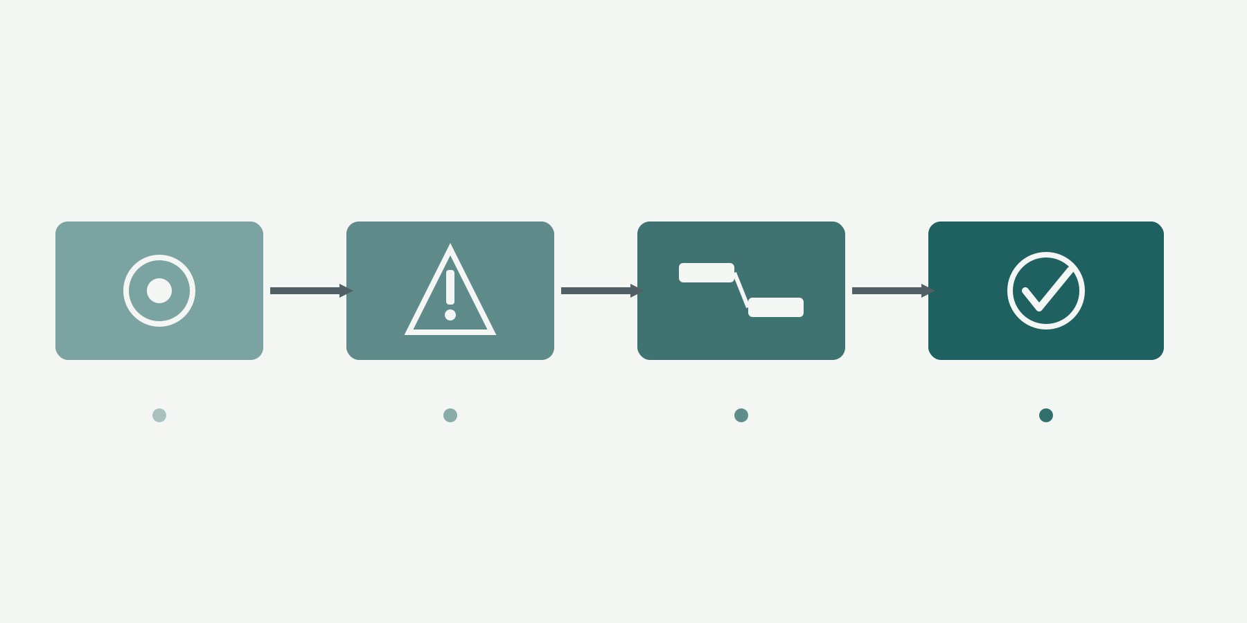
| Feature | Design risk | Manufacturing consequence | Review action |
|---|---|---|---|
| Blind hole / thread | Depth callout unclear; no bottom clearance | Short threads, chip packing, tap risk | Separate full-diameter depth, complete thread depth and tip/clearance zone |
| Deep pocket / small corner | Corner radius forces tiny cutter at full depth | Long reach, chatter, high cycle time | Review corner R with pocket depth and planned cutter diameter |
| Thin wall / tall rib | Height-to-thickness high; poor support | Deflection, scrap, slow finishing | Check support, sequencing and whether thickness is functionally required |
| Tight tolerance on non-critical face | Tolerance not tied to fit or seal | Extra passes, CMM load, false rejects | Keep functional tolerances; relax cosmetic/stock faces |
| Cross-hole / inclined entry | Breakout burr, tip wander | Deburr access, drill breakage risk | Plan entry condition, breakout and cleaning access |
Jump by topic: holes · threads · pockets · thin walls · tolerances.
1. How CNC Manufacturing Constraints Shape Part Design
Design for CNC machining means matching CAD intent to rotating tools, workholding and inspection—not only to a pretty solid model. For process overviews and material context beyond this DFM focus, see the CNC machining handbook.
1.1 What Design for CNC Machining Means
DFM here is a pre-release review: tool access, setups, feature geometry, tolerances and drawings that a shop can quote and produce stably. It is not a promise that every “recommended ratio” fits every material and machine.
1.2 Tool Access and Cutting Direction
Most milling and drilling approaches features from a limited set of directions. Align primary features with principal axes when possible. Features that require many reorientations add setup cost and datum stack-up.
1.3 Rotating Tool Geometry and Internal Features
End mills and drills are cylinders with finite flute length. Internal vertical corners inherit a radius; blind holes drilled with a twist drill inherit a conical point unless a flat bottom is specified and tooled.
1.4 Workholding, Setups and Datum Transfer
Every clamp and flip transfers variation. Design clamping surfaces that do not crush thin sections, and define datums that can survive multiple setups when five-axis or tombstone strategies are not available.
1.5 Machine Capability vs. Economical Production
“Technically possible” is not “economical in repeat production.” Special tools, micro cutters and extreme depth-to-diameter ratios may run once for a prototype and still be wrong for volume.
1.6 Prototype Design vs. Repeat Production
Prototype freedom (tiny radii, deep pockets, many setups) often becomes production pain. Freeze a production-intent revision before tooling and gauges are locked.
| Part feature | Likely tool impact | Workholding / setup | Inspection note |
|---|---|---|---|
| Deep narrow pocket | Long-reach end mill; chip evacuation | May need soft jaws / support | Wall thickness and finish hard to probe in situ |
| Precision bore | Bore / ream after qualified pre-hole | Prefer same setup as critical datums | Size + position + cylindricity plan |
| Blind internal thread | Tap or thread mill + depth clearance | Chip exit strategy | Go/no-go + incomplete thread zone |
| Thin tall wall | Light radial engagement; sharp tools | Support ribs or sequential release | Measure after unclamp if springback risk |
2. Plan Tool Access, Setups and Workholding
Stabilize how the part is held and approached before polishing local dimensions.
2.1 Identify Machining Directions
Sketch which faces are cut from +Z, −Z and side approaches. Features that cannot be reached without undercut tooling need an early process decision.
2.2 Reduce Unnecessary Reorientations
Group features that share a direction. Fewer flips usually mean better relative positions and less non-cutting time.
2.3 Provide Practical Clamping Surfaces
Leave stock or pads that a vise or fixture can grip without crushing functional walls. Soft jaws and vacuum fixtures help, but they do not erase a design that has nowhere solid to hold.
2.4 Leave Clearance for Tools, Holders and Fixtures
Check holder collision near tall bosses and deep cavities. A cutter that “fits” in CAD may still collide when the holder and spindle nose are modeled.
2.5 Consider Long Tools and Deep-Reach Features
Long stick-out reduces stiffness. If depth is unavoidable, expect slower feeds, more passes and tighter process control—or redesign access.
2.6 Plan Datums Across Multiple Setups
State which datums are established in which setup. Critical relationships should be machined in one setup when positional accuracy matters.
2.7 When Indexed or Simultaneous Five-Axis Machining Helps
Five-axis can reduce setups and improve access, but it does not remove tool-geometry limits inside cavities. Treat it as a process option after access and function are clear—not as a default fix for every complex solid.
3. Hole Design for CNC Machining
Holes drive drills, boring bars, reamers and combination tools. Clear callouts prevent shops from guessing which depth is functional.
3.1 Through Holes vs. Blind Holes
Through holes usually simplify chip exit, cleaning and threading. Blind holes need explicit depth references and a defined bottom condition.
3.2 Selecting Hole Diameters
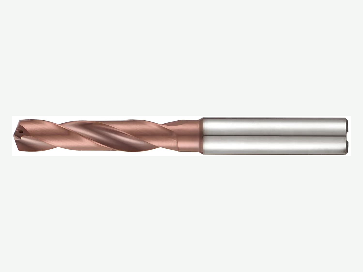
Prefer standard drill diameters when function allows. Non-standard sizes may require interpolation, boring or special tools. For carbide drill series selection in metal work, start from process capability—not from a catalog curiosity.
3.3 Hole Depth and Depth-to-Diameter Ratio
Depth-to-diameter (L/D) governs wander, chip packing and peck strategy. Shops often treat roughly 3–4×D as routine twist-drill territory and deeper holes as peck or specialized drilling—but the real limit depends on material, coolant, tool and required exit accuracy. There is no universal safe L/D for every alloy and machine. When peck cycles become the default, see when peck drilling is required.

3.4 Drill Point Geometry and Blind-Hole Bottoms
A conventional twist drill leaves a conical point. Dimension the full cylindrical (full-diameter) depth separately from total drilled depth that includes the point. Do not assume the cone counts as usable bore for a mating pin or fastener.

3.5 Flat-Bottom Holes and Additional Operations
A required flat bottom usually means an end mill, flat-bottom drill or secondary operation—not a standard twist-drill finish. For tooling options on blind flats, see flat-bottom carbide drills for blind holes.
3.6 Counterbores, Countersinks and Spotfaces
These are different features with different tools and inspection. Use the correct callout and standard where applicable; compare forms in counterbore vs countersink vs spotface. For edge-break tooling choices, see countersink vs chamfer mill.
3.7 Holes on Angled or Curved Surfaces
Inclined entry invites tip wander. Spotfacing, center drilling or a pilot strategy is often required before the production drill. Cross-holes and thin-wall exits need breakout planning—see carbide drilling of inclined and cross holes in thin walls.
3.8 Intersecting Holes and Breakthrough Conditions
Intersections create burrs, thin webs and cleaning challenges. Specify which hole is primary, whether breakout is allowed and how burrs are controlled.
3.9 Hole Position, Straightness and Finished Size
Position relative to datums, straightness over depth and finished diameter are separate requirements. Drilling alone may not hold tight size; boring or reaming may follow a qualified pre-hole.
3.10 When Boring or Reaming Is Required
Use boring/reaming when size, roundness or finish exceeds what drilling can hold under your material and L/D.
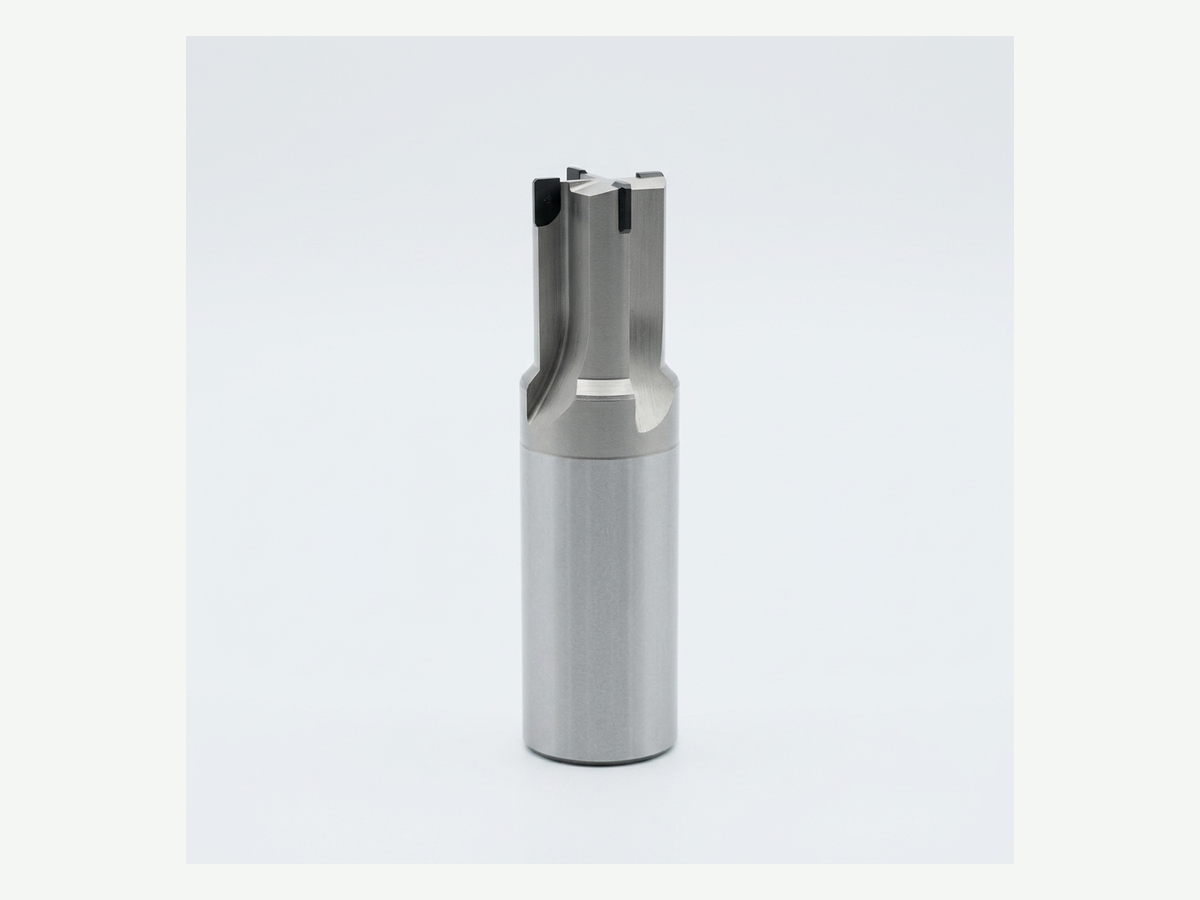
Pre-hole quality dominates reamer success—see PCD reamer pre-hole quality (PCD applies to aluminum and other non-ferrous materials—not steel, stainless, cast iron or hardened steels). For process selection between separate and combination routes, see when to use a combination drill-reamer. Tool options include solid carbide drills, through-coolant carbide drills, combination drill-reamers and PCD reamers (non-ferrous only).
| Hole situation | Typical tooling path | Design callout to clarify |
|---|---|---|
| Plain clearance hole | Drill (standard size) | Through/blind; diameter; depth reference |
| Blind functional bore | Drill + (optional) flat bottom / bore | Full-diameter depth vs total depth; bottom shape |
| Precision location / size | Drill → bore/ream | Tolerance class; position; pre-hole expectation |
| Deep chip-sensitive hole | Through-coolant / peck strategy | L/D; coolant access; breakout |
4. Thread Design and Manufacturing
Thread callouts must separate fastener engagement needs from manufacturing space below the last full thread.
4.1 Define Thread Standard, Size, Pitch and Class
State metric/unified (or other) standard, size, pitch and class/fit. Incomplete 3D helixes in CAD are not a substitute for a clear drawing note.
4.2 Internal vs. External Threads
Internal threads need tap drill, chip strategy and bottom clearance. External threads need relief/runout space at shoulders when a full thread is required to a face.
4.3 Through Threads vs. Blind Threads
Through threads simplify chip exit. Blind threads require planned incomplete-thread and chip zones.
4.4 Thread Engagement vs. Total Thread Depth
Engagement length is a joint-design decision based on materials, loads and fastener practice. It is not the same as “drill this deep and tap to the bottom.” Do not replace strength design with a single universal “N× diameter” rule without stating material and loading conditions.
4.5 Tap Drill Depth and Bottom Clearance
Provide clearance below the last full thread for tap lead, chip space or thread-mill runout—tool-dependent. Dimension complete usable thread depth separately from drilled depth.
4.6 Thread Entry Chamfers and Incomplete Threads
Entry chamfers help starting and reduce first-thread damage. Incomplete threads at the bottom of a blind hole are normal for many taps; call out what is complete vs. incomplete.
4.7 Tapping vs. Thread Milling
Tapping is fast in many production holes; thread milling offers diameter adjustability and often better chip control in blind holes or difficult materials. For aluminum-specific trade-offs, see thread milling vs tapping in aluminum.
4.8 External Thread Relief and Tool Runout
If a full thread must run to a shoulder, add a relief groove sized for the threading tool. Otherwise accept incomplete threads near the shoulder.
4.9 Thin-Walled Threaded Features
Thin bosses can bulge during tapping. Check wall around the major diameter, insert options and whether an external nut plate is wiser than a tiny tapped boss.
4.10 Thread Inspection and Drawing Requirements
Define go/no-go, pitch diameter method or functional gauge expectations. Include revision-controlled notes for thread forming vs cutting when that choice is constrained.
5. Pockets, Slots and Internal Corners
Pockets couple depth, width, corner radius and chip evacuation. Corner radius and cutter diameter must be reviewed together.
5.1 Pocket Depth, Width and Tool Reach
Deep, narrow pockets force long slender tools. A common planning check is whether a finishing cutter can reach the floor with acceptable stick-out for the material and tolerance—not a single universal depth/width limit for every shop.
5.2 Internal Corner Radii and Cutter Diameter
A rotating end mill cannot cut a perfectly sharp internal corner. Minimum corner radius equals the tool radius; specifying a slightly larger radius than the planned tool radius often allows a cleaner sweep and less full-width engagement. Exact “1.3× tool radius” heuristics are starting points—validate against function and mating parts.
5.3 Why Tool Radius and Corner Radius Should Be Reviewed Together
Example (illustrative geometry, not a shop guarantee): a 24 mm-deep pocket with R2 corners admits a corner-finishing cutter no larger than about Ø4 mm at that corner—high depth-to-diameter before holder clearance. Opening to R4 may admit a larger cutter if assembly still fits. Always re-check stress and mating clearances.
5.4 Deep and Narrow Pockets
Expect chip packing, deflection and finish risk. Options include opening the mouth, stepping depth, machining from two sides or splitting the part—after functional review.
5.5 Slot Width, Depth and End Geometry
Match slot width to available cutters when possible. Slot ends may be radius (cutter diameter) or require secondary shaping.
5.6 Pocket Floors, Wall Transitions and Remaining Material
Floor-to-wall fillets differ from vertical corner radii. Call out floor radii only when function needs them; otherwise let process choose an economical tool nose.
5.7 Chip Evacuation and Coolant Access
Closed deep pockets need a chip strategy (air, flood, through-tool where applicable). Design can help by avoiding dead-end chip traps.
5.8 Corner Reliefs for Mating Components
If a square insert must seat, consider dog-bone or corner relief rather than forcing an impossibly sharp milled corner.
5.9 When Splitting a Part or Changing the Process Helps
Assemblies, EDM or cast near-net shapes can beat impossible internal geometry. Decide before volume tooling is ordered.
| Design feature | Cost / risk driver | Possible alternative | Functional check |
|---|---|---|---|
| Tiny internal R at deep floor | Micro cutter at long reach | Larger R; relief notch; two-side machining | Mating part / stress concentration |
| Closed deep pocket | Chips + coolant access | Open side; drain features | Sealing / strength |
| Sharp internal square corner | EDM / broach / relief | Dog-bone relief | Insert seating |
6. Thin Walls, Slender Features and Distortion
Thin features fail by deflection during cutting and by spring-back after unclamping. Thickness alone is not enough—height, unsupported span, material and cutting direction matter. There is no universal minimum wall thickness that is safe for every material and height.
6.1 What Counts as a Thin Wall
Treat walls as thin when height-to-thickness is high, when they are poorly supported at ends, or when residual stress will release during machining. Industry “starting points” (often cited near ~0.8 mm metals / ~1.5 mm plastics for short walls) are guidance only—state material, height and tolerance before adopting them.
6.2 Height-to-Thickness and Support
Taller unsupported walls need more conservative thickness or temporary ribs. Ribs can be machined away in a final pass when function allows.
6.3 Workholding Distortion
Clamp forces can dish thin floors and walls. Design pads, specify gentle fixturing notes or sequence roughing so critical walls finish after support is reduced carefully.
6.4 Machining Sequence and Stress Relief
Uneven stock removal releases stress. For critical flatness, plan rough → stress-relieve (if required) → finish, and measure after unclamp.
6.5 Slender Bosses, Pins and Tall Ribs
Slender features chatter and taper. Prefer larger root fillets, shorter height or secondary forming only when justified.
6.6 Thin Floors Under Pockets
Thin floors bow under cutting and vacuum/clamp loads. Keep a supported section, add ribs or change the pocket layout.
6.7 Plastics vs. Metals
Engineering plastics often need thicker walls because of lower stiffness and residual stress in plate stock. Metals may allow thinner sections but still chatter when tall and unsupported.
| Risk signal | Why it hurts | Design / process response |
|---|---|---|
| High H/t unsupported wall | Chatter, taper | Thicken, shorten, rib, light radial cuts |
| Thin floor under deep pocket | Bow, thickness out of tol. | Ribs; leave stock; sequence |
| Clamp on thin section | Crush / dish | Clamp pads; soft jaws; fixture redesign |
7. Turned Features: Shoulders, Grooves and Concentricity
Rotational parts still need DFM: tool access, reliefs and datum strategy.
7.1 Shoulder Heights and Tool Clearance
Sharp inside corners at shoulders may need undercut/relief for facing and turning tools.
7.2 Grooves, Snap Rings and O-Ring Lands
Prefer standard groove widths matching available tooling. State seal standards when used.
7.3 Concentricity and Datum Strategy
Critical OD/ID relationships prefer one chucking. Cross-drilled holes after turning need position callouts relative to turned datums.
7.4 Live Tooling and Mill-Turn Features
Flats, keyways and cross-holes on turned blanks can stay in one setup on mill-turn equipment—design so those features share a coherent datum story.
8. Tolerances, Datums and What to Tighten
Tolerances buy process capability and inspection—not status. Tie each tight callout to function.
8.1 Functional Tolerances vs. Default Shop Tolerances
If no tolerance is stated, shops apply a general class (for example ISO 2768 medium/fine—when that system is specified). Do not assume a global “±0.1 mm everywhere” without stating the system.
8.2 Choose One Rule System
ISO GPS and ASME Y14.5 GD&T are different rule systems. Pick one drawing convention and stay consistent. Mixing symbols and default rules without a stated hierarchy creates ambiguous parts.
8.3 Datums That Match How the Part Locates in Assembly
Datums should reflect assembly and inspection, not only CAD origin convenience.
8.4 Position, Size and Form
Separate size from position and form. A reamed H7 hole is a size story; pattern location is a position story—see reamer tolerance for H7 holes when size class is the issue.
8.5 Stack-Ups Across Setups
Tight position across faces machined in different setups may need process change (fewer flips, better fixtures or multi-axis) rather than a hopeful tolerance balloon.
8.6 Inspection Access
If a feature cannot be probed or gauged, the tolerance is not production-ready. Redesign access or change the measurement plan.
| Callout type | When to use | Common mistake |
|---|---|---|
| General tolerance block | Non-critical dimensions | Leaving critical fits to the block |
| Plus/minus on size | Fits, thicknesses | Ignoring form/position needs |
| GD&T / GPS position | Patterns, assembly location | Mixing ISO and ASME defaults |
| Surface texture | Seal/bearing faces | Mirror finish on non-functional faces |
9. Surface Finish, Edges and Burr Control
Finish and edges are design requirements when they affect sealing, fatigue, assembly or safety.
9.1 As-Machined vs. Functional Finishes
Standard as-machined texture is often acceptable on non-functional faces. Call out finer Ra only where friction, sealing or appearance truly requires it.
9.2 Edge Breaks vs. Critical Edge Geometry
A generic “break all sharp edges” note is not enough for sealing edges, knife edges or fatigue-critical corners. Specify chamfer/radius where function cares.
9.3 Exit Burrs on Holes and Cross-Holes
Exit burrs are predictable at breakthroughs. Design cleaning access; for aluminum reaming exits, see aluminum exit burr control in reaming.
9.4 Internal Edges at Intersections
Cross-holes create internal ridges. State whether they must be free of burrs and how that will be verified.
10. Material Selection and Its Effect on Design
Material changes stiffness, residual stress, tool wear and achievable thin-wall behavior. This chapter is a design bridge—not a materials encyclopedia (use the handbook and material-specific pages for grade detail).
10.1 Strength, Stiffness and Feature Geometry
Higher strength does not automatically allow thinner walls if cutting forces and chatter dominate.
10.2 Material Condition and Dimensional Stability
Call out temper/condition. Stress-relieved plate behaves differently from as-cast or heavily cold-worked stock.
10.3 Aluminum, Steel, Stainless and Titanium
Aluminum often machines freely but deflects when thin. Steels and stainless raise cutting forces and heat. Titanium needs careful heat and engagement management. Feature guidelines must be restated per family.
10.4 Copper Alloys and Engineering Plastics
Copper alloys may be gummy; plastics move with moisture and residual stress. Wall and tolerance strategies change accordingly.
10.5 Stock Form, Allowance and Material Removal
Buy-to-fly and blank choice affect both cost and distortion. Large removal from one face can bow thin parts.
10.6 When a Material Change Requires a Design Review
Switching from aluminum to stainless (or metal to plastic) is a DFM event: revisit walls, holes, threads, feeds expectation and inspection.
| Material characteristic | Features most affected | Re-check |
|---|---|---|
| Low stiffness / residual stress | Thin walls, flatness | Thickness, ribs, sequence |
| Work hardening | Holes, taps | Tool path, peck, coolant |
| High strength / heat | Deep pockets, long tools | Engagement, reach, finish passes |
11. Design Choices That Drive Machining Cost
Design sets much of the cost structure; detailed estimation belongs in the CNC machining cost guide. This chapter maps design levers only—no invented percentage savings.
11.1 Extra Setups and Difficult Workholding
Each flip adds labor and risk. Awkward shapes without clamp faces drive custom fixtures.
11.2 Small Tools and Long Reach
Tiny cutters and long stick-out multiply passes and slow feeds.
11.3 Deep Holes and Deep Pockets
Depth drives specialty drills, pecking, long mills and chip strategies.
11.4 Tight Tolerances and Demanding Finishes
Tighter than function requires buys inspection and scrap probability.
11.5 Special Tools and Additional Operations
Flat bottoms, undercuts, micro threads and non-standard forms add tools and ops.
11.6 Inspection Access and Measurement Complexity
Hidden features that need CMM gymnastics are a cost driver.
11.7 Prototype vs. Production Design Trade-Offs
What is fine for one article may be wrong at volume. Plan the production revision intentionally.
11.8 When Custom Tooling Is Economically Reasonable
Custom drills, step tools or form tools can win when volume and stability justify them—evaluate on shared trial data, not catalog hope. HENTRY supports tooling and process consultation; HENTRY does not quote full CNC job-shop part manufacturing for your finished component.
| Design change | Manufacturing impact | Functional risk | Validation required |
|---|---|---|---|
| Increase internal corner R | Larger cutter possible | Mating clearance / stress | Fit check; FEA if loaded |
| Clarify blind depth callouts | Fewer tap/ream surprises | Engagement length | Fastener stack review |
| Add clamp pads | Stable workholding | Mass / envelope | Assembly envelope |
| Relax non-critical tolerance | Fewer finish passes | None if non-functional | Confirm function map |
12. CAD Models, Drawings and RFQ Preparation
Clear packages reduce quote risk and wrong parts.
12.1 Keep the CAD Model and Drawing Consistent
Revision letters must match. Threads, tolerances and finishes that live only in a silent 3D attribute will be missed.
12.2 Specify Material Grade and Condition
Include standard designation and temper/condition.
12.3 Identify Critical Features
Mark CTQ features explicitly.
12.4 Define Hole and Thread Requirements
Through/blind, depths, bottom shapes, thread standards and incomplete zones.
12.5 State Tolerances, Datums and Surface Requirements
General block + critical callouts + texture where needed.
12.6 Clarify Heat Treatment and Finishing
Sequence matters (machine → heat treat → finish machine, etc.).
12.7 Include Revision, Quantity and Inspection Requirements
Quantity, FAI needs and gauge expectations change process choice.
12.8 Resolve Ambiguities Before Production
Open questions at RFQ become scrap later. Separate machined-part RFQ packages (for your machine shop) from cutting-tool / process RFQs (for HENTRY tooling consultation).
13. Worked DFM Examples
All examples below are teaching / illustrative geometries—not anonymized customer case studies and not validated production results.
13.1 Blind Threaded Hole: Depth and Bottom Clearance
Intent: M6 blind thread with defined complete thread depth. Risk in vague model: CAD shows a helix to the floor; shop drills short or taps into packed chips. Review: dimension complete thread depth, tap-drill depth and clearance; confirm fastener engagement against materials. Validate: gauge + section check on first articles.
13.2 Deep Pocket: Corner Radius and Tool Reach
Intent: Structural pocket. Risk: R1 corners at 30 mm depth force a tiny long tool. Options: open corners if mating allows; machine from two sides; accept specialty tooling with trial. Validate: cutter stick-out study and chatter check.
13.3 Thin-Walled Housing: Support and Dimensional Stability
Intent: Light housing. Risk: walls deflect in cut and after unclamp. Options: local thicken, ribs, clamp pads, sequential release. Validate: measure critical diameters free-state.
13.4 Precision Bore: Tolerance, Process and Inspection
Intent: Bearing bore size + position. Risk: drill-only process. Options: qualified pre-hole + bore/ream; same-setup datums. Validate: size gauge + position CMM.
13.5 Cross-Hole Component: Breakthrough and Deburring
Intent: Lubrication cross-hole. Risk: internal burrs block flow. Options: specify deburr method and inspection; adjust intersection timing. Validate: flow or borescope check as required.
13.6 Turned Shaft: Shoulders, Grooves and Datum Relationships
Intent: Shaft with snap-ring groove and critical journal. Risk: missing relief; groove non-standard; journal/datum mismatch after re-chuck. Options: standard groove; relief; one-setup journals. Validate: runout and groove gauge.
14. Frequently Asked Questions
What are the main design rules for CNC machining?
Give tools access, hold the part without crushing it, use corner radii and hole depths that match realistic cutters, and tighten tolerances only where function and inspection require. Treat published “limits tables” as conditional starting points—not universal laws.
How should internal corner radii be selected?
Never smaller than the planned finishing cutter radius. Slightly larger than the tool radius often machines cleaner. Re-check mating parts and stress before opening a corner only to save cycle time.
How deep can a CNC-machined pocket be?
Depth is a tool-reach and chip-evacuation decision for your material and tolerance—not a single global multiple of width. Deep, narrow pockets with tiny corners are the usual failure mode.
What limits the minimum wall thickness?
Height, unsupported span, material stiffness/residual stress, cutting forces and required tolerance. There is no universal minimum thickness that is always safe.
How should blind-hole depth be specified?
State full-diameter (cylindrical) depth separately from total depth that includes a drill point, and state whether the bottom must be flat.
How much clearance is needed below a blind thread?
Enough for the selected tapping or thread-milling tool’s lead, chip space and incomplete-thread zone. Clearance is tool- and process-dependent—confirm with the threading method you will actually run.
When should a hole be bored or reamed?
When finished size, roundness or surface needs exceed a reliable drilled result under your L/D and material. Pre-hole quality is part of the design/process package.
Which features need tight tolerances?
Fits, sealing faces, bearing bores and assembly-critical positions. Cosmetic or stock faces rarely do.
When does five-axis machining simplify a design?
When it removes setups or reaches compound angles without losing datums. It does not eliminate internal tool-radius limits.
What should be included in a CNC machining drawing?
Material and condition, datums, critical tolerances (one rule system), hole/thread details with depths, finishes, HT/coat sequence, revision and inspection notes—consistent with the CAD model.
Appendix — Checklists and Templates
The following worksheets are planned companion tools. They are available on request with a tooling/process discussion—no public download URLs are published on this page.
| Appendix | Name | Purpose |
|---|---|---|
| A | CNC DFM Review Checklist | End-to-end design review |
| B | Hole and Thread Design Checklist | Depths, bottoms, engagement vs clearance |
| C | Pocket and Tool Access Review Sheet | Reach, corners, chips |
| D | Thin-Wall Risk Assessment | Support, clamp, distortion |
| E | Tolerance and Inspection Planning Sheet | Function → tolerance → method |
| F | Drawing and RFQ Checklist | Quote-ready package |
| G | Annotated DFM Examples | Teaching callouts (illustrative) |
Discuss feature access, hole/thread callouts or tooling options with HENTRY. Share drawings for cutting-tool and process consultation—not for full job-shop part quoting.