
The part drawing says Ø10 H7, and someone now has to turn that into a reamer: the buyer filling in the RFQ, the process engineer drawing a special tool, or the distributor passing the job to a tool maker. The quick move is to copy the hole limits onto the tool drawing, 10.000 to 10.015 mm, and treat the job as specified. The tool maker can then grind the reamer anywhere inside those 15 µm and still meet the print. If it lands near the bottom of the band, the first few µm of wear take the hole undersize, and because the tool matches what was written, the buyer owns the problem.
H7 is the tolerance of the hole. The reamer that makes the hole needs its own, narrower diameter band, and that band sits in the upper part of the hole band. DIN 1420 and ISO 522 give the standard way to position it. On special jobs such as aluminum housings, thin walls or PCD tools, the band may move after a trial. The sections below cover how the standard band is placed, what shifts it, how to write it on a custom-tool drawing, and what to send if you want XRZ to set it for you.
H7 describes the hole: the lower deviation is zero and the band is one IT7 wide, so 10H7 means 10.000 to 10.015 mm. A reamer for that hole needs its own, narrower diameter band inside the upper part of the hole band; DIN 1420 gives 10 +0.012/+0.006 mm for a 10H7 reamer. Material, runout, pre-hole and measuring temperature can shift that band on special jobs, so the final tool band is confirmed on first-article parts.
H7 Is the Hole Tolerance, Not the Reamer Tolerance
In ISO 286, a capital letter describes a hole and the number is the tolerance grade. H means the lower deviation is zero, so an H hole is never smaller than nominal. The 7 means the band is one IT7 wide, and IT7 grows with diameter:
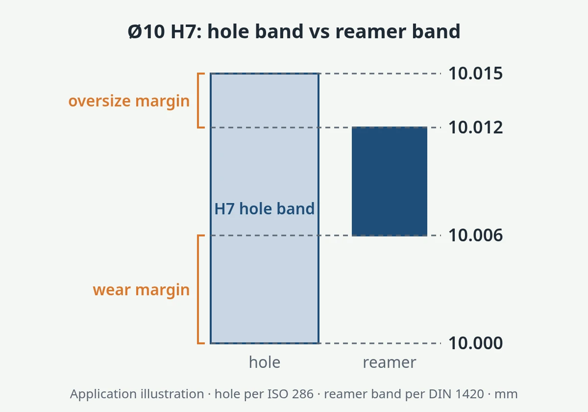
Hole tolerance per ISO 286-2, not the reamer band.
| Nominal size (over … up to and including) | IT7 hole-band width | Example H7 hole |
|---|---|---|
| over 3 to 6 mm | 12 µm | Ø6 H7 = 6.000 – 6.012 mm |
| over 6 to 10 mm | 15 µm | Ø10 H7 = 10.000 – 10.015 mm |
| over 10 to 18 mm | 18 µm | Ø12 H7 = 12.000 – 12.018 mm |
| over 18 to 30 mm | 21 µm | Ø20 H7 = 20.000 – 20.021 mm |
Ø10 falls in the "over 6 to 10" range because each range includes its upper limit. Putting Ø10 in the 10–18 row is a common slip, and it gives a band 3 µm too wide.
All of these numbers describe the finished hole, measured in the part. The reamer is a separate feature: its cutting diameter is measured on the tool, before it ever touches the part. A reamer does not cut exactly its own diameter. A new, sharp tool with some runout can cut slightly larger. A worn tool, or a material that closes up after the edge passes, leaves the hole smaller. For that reason "Reamer Ø10 H7" on a special-tool drawing does not tell the tool maker what diameter to grind. It tells them what hole you want and leaves the tool band to guesswork.
What Size Reamer for an H7 Hole (DIN 1420 / ISO 522 Logic)
DIN 1420 (reamers: manufacturing tolerances and designation) and ISO 522 (special tolerances for reamers) both set the reamer band from the hole band rather than copying it. ISO 522 recommends its method for special reamers where possible, which covers most custom tools. The result has three features:
- The reamer band is narrower than the hole band.
- It sits in the upper part of the hole band, not across all of it.
- It stops below the hole's upper limit, so a new tool that cuts slightly over its own size still leaves a hole inside tolerance.
For a 10H7 hole, DIN 1420 gives a reamer diameter of 10 +0.012/+0.006 mm, or 10.006 to 10.012 mm. Put that next to the hole limits of 10.000 to 10.015 mm. The tool band is 6 µm wide against 15 µm for the hole. Subtracting the reamer band (10.006–10.012 mm) from the hole band (10.000–10.015 mm) leaves 3 µm between the top of the reamer band and the top of the hole for a new tool that cuts slightly oversize, and 6 µm between the hole's lower limit and the bottom of the reamer band for wear before the hole goes undersize.
That is the one worked example this page gives. For other diameters and grades, read the band from a current copy of DIN 1420 or ISO 522, or ask your tool supplier to state it. Do not scale the 10 mm numbers to another size, and do not rebuild the table from a catalog scan. Reamer types and how the finished-bore requirement drives the choice of tool are covered on the reamer tools page. If the drawing asks for IT6 or tighter, or the real problem is hole position rather than size, a fixed-size reamer may be the wrong finishing route; see reaming vs boring for precision holes.
Why a reamer ground to the full H7 band fails
If the tool drawing carries the hole band, a tool made anywhere inside it passes inspection, and the trouble depends on where it lands:
- Near the lower limit: there is almost no wear margin. The first few µm of edge wear, or a material that springs back after the cut, take the hole below 10.000 mm.
- Near the upper limit: any cutting over size from runout, lead geometry or a sticky material pushes the hole past 10.015 mm from the first part.
- In the middle: it may work, but nobody chose that position, so the next tool from the same drawing can land somewhere else.
In each case the tool maker has met the drawing. A dispute over a tool that measured in tolerance is hard to win. You avoid it by writing the tool band as its own line.
What Shifts the Reamer Band Away From the Standard
ISO 522 says plainly why its band is a starting point rather than a universal answer. The size of a reamed hole also depends on the workpiece material and the stock removed, the reamer's cutting geometry, its condition, how it is mounted and used, and lubrication. No standard tolerance can cover all of that. On a production job, these are the usual reasons to move the band:
- Material behavior. Some materials close up slightly after the edge passes (springback), so the hole comes out smaller than the tool. Soft or sticky materials can smear or build up on the edge and cut larger. Which way it goes depends on the alloy and condition, not on the tool label.
- Thin walls and clamping. A thin section can deflect under clamping or cutting load and spring back when released. The hole measured in the fixture and the hole measured on the bench can differ. Write down which one counts.
- Interrupted and cross holes. Where the reamer crosses a port or a gap, it loses support and can cut a different size in that zone.
- Runout and holder. Assembled runout makes the effective cutting diameter larger than the diameter measured on the tool. Check this before anyone regrinds or re-orders. The measuring method is in the PCD reamer presetting and runout checklist.
- Allowance. Too little stock and the edge rubs instead of cutting; too much and the load and heat change the result. The numbers belong to PCD reamer allowance and pre-hole size.
- Coolant and lead geometry. The coolant type and delivery, and the lead or chamfer angle, both affect how the edge enters and how closely the hole follows the tool.
Move the band only for a measured reason: a trial result, a known springback direction on that part, or a documented measuring condition. A guessed offset on the first tool just moves the problem to the second one.
Measured cold vs cut warm (why aluminum holes read undersize)
Aluminum expands more than steel for the same temperature rise. A housing reamed while still warm from roughing, or from the cut itself, is at its larger warm size when the reamer passes. As it cools to room temperature, the bore shrinks and reads smaller than it was cut. The reamer was fine; the measurement and the cut took place at different temperatures.
ISO 1 sets 20 °C as the reference temperature for dimensional specifications. Write the measuring temperature, or the time and place of measurement, on both the part requirement and the tool drawing. Otherwise a tool band that is right for the process gets "corrected" to match a cold reading. If the bore is already running undersize, work through the diagnosis in why a PCD reamer produces an undersize hole before any diameter compensation is decided.
When the hole reads oversize
First confirm the reading: the gauge, the setting master, the measuring depth and the part temperature. Then look at assembled runout and the effective cutting diameter before you look at the tool's own band. Oversize, taper and ovality each point to different causes. The diagnosis tree is in how PCD reamers control hole accuracy and surface finish. If the drilled pre-hole is already oversize or off position before the reamer arrives, fix that upstream; for carbide drills, see oversized holes with a new carbide drill. Change the reamer band only when the tool itself is shown to be the cause. The full diagnosis order for an oversize bore is in how to diagnose a reamer cutting oversize.
How to Write Reamer Tolerance on a Custom Tool Drawing
A clear tool drawing and RFQ carry two separate lines, one for the hole and one for the tool, plus how both are measured.
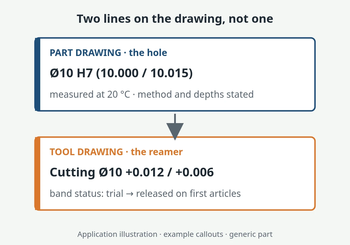
1. The hole requirement (from the part drawing). Write the fit and the limits: Ø10 H7 (10.000 / 10.015). Add the other bore requirements that matter, such as roundness, cylindricity, surface finish and depth.
2. The tool band. Choose one of two ways:
- State it:
Cutting Ø 10 +0.012 / +0.006 (standard band for 10H7), and say where on the tool the diameter is measured. - Or delegate it:
Cutting Ø: supplier to set for 10H7 hole in [material]; state proposed band on drawing for approval.
Delegating is fine as long as the band comes back to you in writing before the tool is made.
3. How the hole is measured. Air gauge, bore gauge or CMM; how many depths; clamped or unclamped; and at what temperature (20 °C reference, or "measured x minutes after machining at the machine").
4. How the tool is measured. The measuring method and location on the cutting diameter, and the record you expect with the tool. The records worth requiring are listed in what inspection pack to require for a custom PCD reamer.
5. Band status. Mark the band as trial (to be confirmed on first-article parts) or released, with a drawing revision. When a trial moves the band, the new revision replaces the old one, and the next order points to it. The trial-to-release steps are in sample validation.
PCD vs carbide reamer: same logic, different wear behavior
The sizing logic does not change with the cutting material. A PCD reamer for a 10H7 hole starts from the same hole band and the same idea of a narrower tool band in its upper part. What changes is how the band gets used up. PCD is usually chosen where carbide edges wear quickly, such as abrasive aluminum alloys, so the wear margin at the bottom of the band is consumed at a different rate. The question that decides the drawing is what happens at regrind: whether reconditioning touches only the lead or also the cutting diameter, and so whether the tool can come back inside the same band or needs its own reconditioned band. Settle that before the first tool is made. The service side is in the PCD reamer regrind and requalification guide, and whether PCD is the right choice at all is covered in PCD reamer vs carbide reamer.
What to Send XRZ for an H7 Reamer Tolerance Review
If you want us to set or check the reamer band, the hole print alone is a start. These fields let the band be set for your process rather than for a catalog:
- Hole nominal, upper and lower limits, and tolerance grade (for example, Ø10 H7, 10.000 / 10.015)
- Other bore requirements: roundness, cylindricity, surface finish, depth
- Material and condition; for aluminum, the alloy and silicon content if known
- Wall thickness near the bore and how the part is clamped
- Through, blind or cross hole, and reamed depth
- Pre-hole method and its measured size range (minimum and maximum); drill-side tolerance classes are in carbide drill diameter tolerance (m7, h7, h8)
- Machine, holder type and measured assembled runout
- Coolant type and delivery (through-tool or external)
- Inspection method, measuring position and temperature
- If a tool already exists: its measured diameter and the hole sizes it produces, including the trend over the run
- Regrind expectation: reground by you, by us, or replaced
Write "unknown" where a value is unknown. A blank field and an unknown value lead to different questions.
Frequently Asked Questions
What size reamer do I need for an H7 hole?
A reamer whose diameter band sits inside the upper part of the H7 hole band, not one ground to the hole limits. For a 10H7 hole (10.000–10.015 mm), DIN 1420 gives a reamer of 10 +0.012/+0.006 mm. For other sizes, take the band from DIN 1420 or ISO 522, or have the supplier state it in writing.
Can I order a reamer "to H7"?
From a standard catalog, a reamer labelled H7 is made to the standard band for producing an H7 hole, so the label works as shorthand. On a special-tool drawing, H7 alone describes the hole, not the tool, and a tool maker can grind anywhere inside the hole band and still meet the print. Write the tool band as its own line, or state that the supplier sets it and returns it for approval.
Why does my H7 reamer cut oversize or undersize?
Check measurement first: gauge, depth and part temperature. Oversize usually points to runout, lead geometry, pre-hole or material that builds up on the edge. Undersize usually points to springback, wear, too little allowance or a part measured cold after being cut warm. Change the tool band only after the process causes are ruled out and the direction of the error repeats.
Does a PCD reamer need a different tolerance band than carbide?
The sizing logic is the same: a narrower band in the upper part of the hole band. The difference is how the band is used up in service and what the tool comes back as after regrind. Set the PCD band with the material, the measuring method and the reconditioning plan written on the drawing.
Next step
What you want at the end is a tool drawing with two clear lines, the hole you need and the reamer band that makes it, plus a sample run that confirms the band on your parts.
- PCD reamer RFQ checklist, the full field map before you send.
- Custom PCD reamers
- Send your hole print and we propose the reamer band in the quote for your approval.