
Short answer. Most “PCD accuracy” complaints start as holder, clocking, or assembled runout—not the diamond label. Preset length and Ø offsets, verify clocking where the process needs it, measure assembled runout at agreed positions, and after reconditioning re-apply compensation before volume. First-article release should lock this checklist, not tribal memory. Send holder type, gauge length, and runout readings with the bore scrap mode. XRZ reads that pack, writes sample acceptance, and stays on first-off (sample validation → Custom Cutting Tool RFQ).
Opening
First-off comes off lobed. Someone blames the diamond. The holder taper still has yesterday’s swarf, clocking was “close enough,” and nobody measured assembled runout at the stickout the machine actually uses. The edge never got a fair trial.
This page is the preset / clock / assembled-runout checklist for a PCD reamer: unbox to first-article, and again after a regrind. It is not a plant-tour of grinders (how PCD reamers are made). It is not the recondition SOP (when to regrind and how to requalify). Watch the edge on the cutting-edge inspection video; use this list for the holder stack.
1. Unbox, clean, look—before the spindle
Do this on the bench, not after the first scrap tag:
- Confirm tool ID and drawing revision match the job traveler. A “same reamer” from last month may be a different grind.
- Wipe shank, taper, and coolant ports. Swarf in a collet or HSK face is assembled runout you have not measured yet.
- Visual: PCD lips, pads/pilots, obvious nick or raised braze. If the edge is the question, watch cutting-edge inspection and photograph what you see.
- If this tool just returned from service, stop and open the regrind / requalify release note before you copy last month’s offsets.
Holder hygiene and projection habits for create tools are written on carbide drill stickout, runout, and toolholders. The same stack logic applies to a reamer: clean interfaces, only as much stickout as the bore needs, measure the assembly you will actually run.
2. Preset and clocking—fields to record
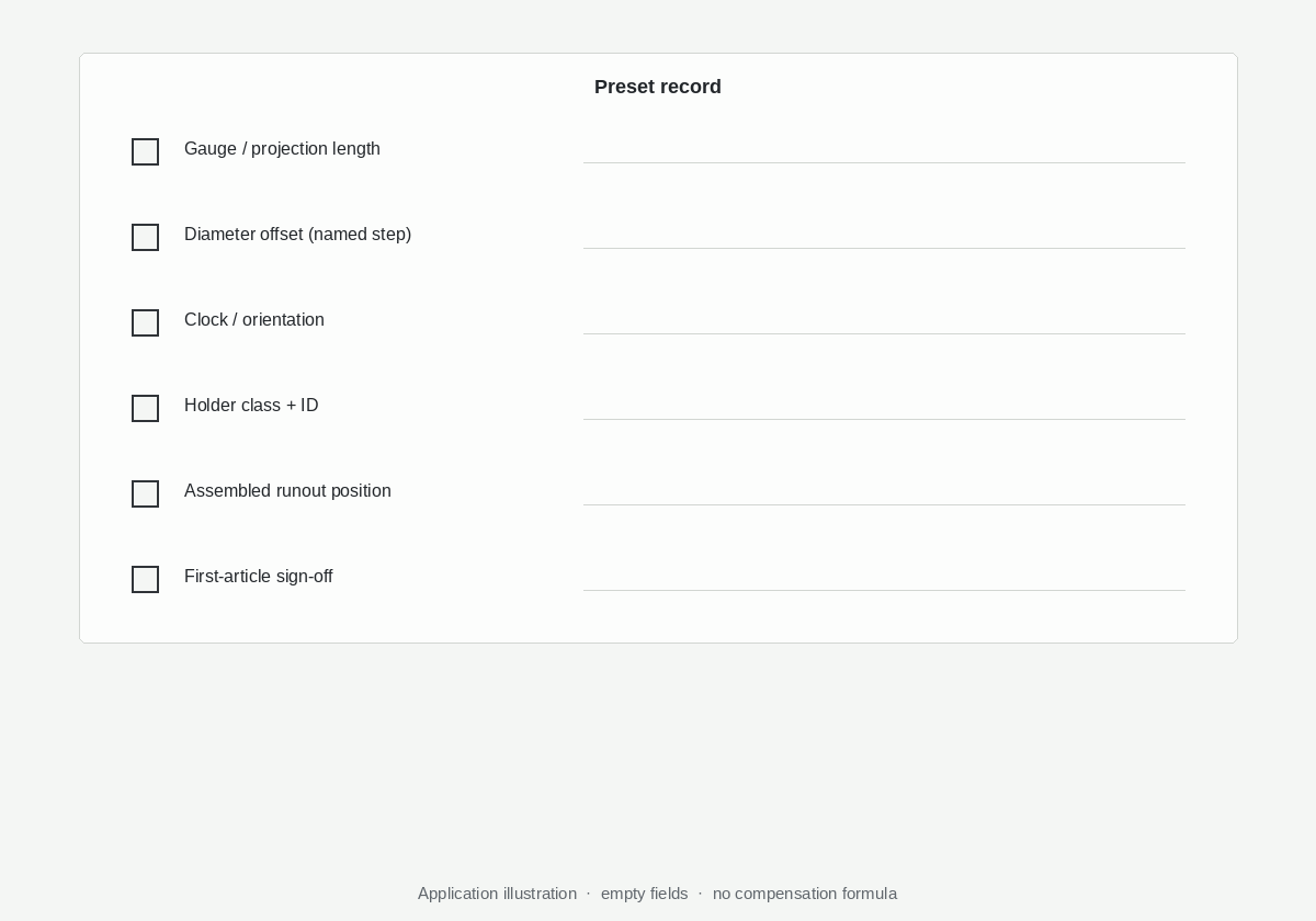
Preset is not “length looks right in the setter.” Write the fields the control and the gauge will use:
| Field | Record | Why it bites later |
|---|---|---|
| Gauge / projection length | Setter value + where it was taken | After regrind the body is shorter; old Z will crash or rub |
| Diameter offset / wear offset | Value + which Ø / step it belongs to | Multi-step tools need a named offset per finish Ø |
| Clock / orientation | Mark vs holder, spindle, or pad clock if the process uses it | A guided or stepped body that is clocked wrong loads one land |
| Holder class + ID | ER / hydraulic / shrink / other + holder number | Published holder TIR is not assembled TIR |
| Setter vs spindle | Which machine, which taper, who signed | A pretty setter number can die on a dirty spindle |
Clocking matters when pads, a pilot, or a step relationship have a preferred orientation—or when you are matching a previous approved assembly. If the process does not use clock, write “not required” so the next shift does not invent one.
Product geometry still comes from the custom PCD reamer drawing, not from a setter default.
3. Assembled runout: where to measure, how to accept
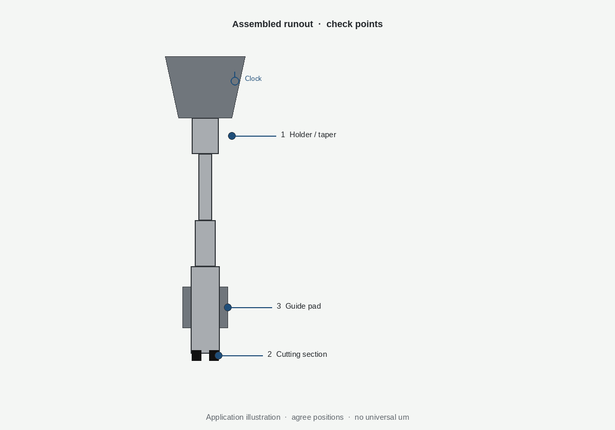
Measure the spindle–holder–reamer stack at the stickout you will cut with. A bench arbor number is a screening value, not the production number.
Where (agree and repeat):
- Near the cutting section (as close to the PCD lips as you can do safely).
- On a guide pad or land if the tool uses one—the bore will follow that contact.
- At a second axial station if the body is long; angular error grows with length.
Holder catalogs publish a component TIR. Once you add a collet, reducer, or extension, the number that matters is cumulative assembled runout at the edge. Errors are directional—they can add or cancel when you clock a component—and length magnifies an angular miss (BIG DAISHOWA, combined TIR in multi-component assemblies—OEM setup practice, not an XRZ accept table).
Accept logic (heuristic, no fake universal µm):
| Question | Accept path |
|---|---|
| Is there a number on the tool drawing or control plan? | That number, at the stated position, wins. |
| Is the scrap mode lobing, one-edge wear, or oversize on a “new” tool? | Treat assembled runout as the first suspect—fix the stack before you redesign the diamond. |
| Did quality collapse only after a holder or stickout change? | Restore the previous assembly as a controlled test. |
| Do you want a website µm band to copy? | There isn’t one on this page. Write the plant number. |
Drill-side measurement practice (qualitative, stricter as Ø shrinks): stickout, runout, and toolholders. Do not import a drill TIR slogan onto a finish reamer and call it validated.
4. After regrind: compensate again
A reconditioned reamer is a new offset event. Stock came off the lips; length changed; sometimes a pad was restored.
Before volume:
- 1. Confirm the service release against regrind and requalify (Ø, runout, pads, edge).
- 2. Re-preset length and Ø. Do not copy the pre-service wear offset.
- 3. Re-check assembled runout on the same holder you will run.
- 4. Re-clock if the process uses clock.
- 5. First-article on the written gauge plan—then release.
If the shop “just put it back in” and the bore moved, the missing step is usually this list, not a new PCD grade.
5. First-article → sample validation / RFQ
Lock the checklist in the traveler:
- Tool ID / revision / service state (new or post-regrind)
- Holder class, ID, gauge length, clock
- Assembled runout: value, position, instrument
- First-article bore result vs the written accept list
- Who signs release
That is the same ownership idea as sample validation: write pass/fail before the argument. Manufacturing control on a new tool still lives on how PCD reamers are made; buyer questions on inspection evidence sit on the buying checklist; custom capability: custom cutting tools.
Setup RFQ pack
- Holder type/class and spindle interface
- Gauge / stickout length
- Assembled runout readings and where they were taken
- Bore scrap mode (lobe, taper, oversize, chatter marks)
- Drawing + material + whether the tool is new or post-regrind
Fields: PCD Reamer RFQ Checklist → Custom Cutting Tool RFQ. Product: Custom PCD Reamer.
The first-off that failed on a dirty taper is a setup story. Send the holder and gauge data; XRZ will not start by inventing a sharper diamond.
Frequently Asked Questions
Where should assembled runout be measured on a PCD reamer?
On the assembled spindle–holder–tool stack, as close to the cutting section as you can do safely, at the stickout you will run. If the tool has a guide pad or land, measure that contact too. A setter arbor number is a screen, not the production value.
Do I need to re-preset after every regrind?
Yes—treat a serviced tool as a new offset event. Length and Ø move when stock comes off. Re-preset, re-check assembled runout, re-clock if the process uses clock, then first-article. Return triggers and requalify fields: regrind guide.
What runout is “good enough”?
The number on your drawing or control plan, at the stated position. There is no universal micrometre band on this page. If scrap is lobing or one-edge wear, fix assembled runout before you redesign the PCD.
What data belongs in an XRZ setup RFQ?
Holder class and interface, gauge/stickout length, assembled runout readings and positions, bore scrap mode, drawing, material, and whether the tool is new or post-regrind → RFQ checklist → RFQ.
CTA
The useful ending is a traveler that already has the holder ID, the runout position, and a name on first-article—not a sharper slogan on the diamond.
- Soft: Cutting-edge inspection video · How PCD reamers are made · Buying checklist · Stickout / runout (drill practice)
- Product: Custom PCD Reamer
- Hard: Sample validation · PCD Reamer RFQ Checklist → Custom Cutting Tool RFQ
- After service: PCD reamer regrind and requalify