Product Detail
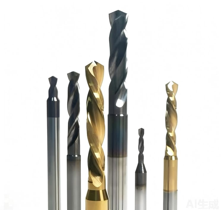
Custom Solid Carbide Drills for Precision and Production Drilling
Drawing-based solid carbide drill manufacturer path for distributors, OEM/ODM and industrial users—depth, coolant, geometry and coating matched to the hole, with RFQ and sample validation.
SOLID CARBIDE DRILL BITS MANUFACTURER
Solid Carbide Drill Bits Manufacturer — Built Around the Hole
Standard drills do not always provide stable results when a component involves unusual hole depths, restricted chip evacuation, stepped features, inclined entry surfaces or repeat-production requirements.
As a solid carbide drill bits manufacturer, XRZ develops custom solid carbide drills around the workpiece material, hole geometry, machine, holder, coolant conditions and production target—for distributors, OEM/ODM brands and industrial end users.
- Standard, semi-standard and custom supply
- Custom diameter, length and point geometry
- Through-coolant, step, chamfer and flat-bottom options
- Application-specific carbide and coating review
- Sample validation before repeat supply
- Distributor, OEM/ODM and private-label programs
Submit your material, hole diameter, depth, tolerance and current machining conditions for a preliminary review.

APPLICATION ENGINEERING
Solid Carbide Drills Developed Around the Hole
A solid carbide drill should be selected as part of the complete machining system—not only by its nominal diameter.
Hole depth, material hardness, entry surface, chip evacuation, coolant delivery, holder runout and machine rigidity can all affect tool wear and hole results. XRZ reviews these conditions before confirming the tool geometry, carbide grade, coating and validation requirements.
Final tool geometry and machining recommendations are confirmed from the drawing and application conditions.
Who We Support
- Cutting-tool distributors expanding a drill range
- Tool brands requiring OEM/ODM manufacturing
- Manufacturers with special hole features
- Process engineers replacing an unstable tool
- Buyers requiring repeatable identification and reorder supply
CONFIGURATIONS
Available Solid Carbide Drill Configurations
Start from the workpiece drawing and machining conditions, then select the structure that best fits the hole.


Standard Twist Drills
For conventional hole-making where diameter, depth and entry conditions suit a standard drilling structure. Availability and stock are confirmed at quotation.
WHAT TO SEND
Unified RFQ packet (then open the specialist checklist)
Send drawing, material (Si% if aluminum), hole/bore data, machine/holder/runout, coolant and failure photos. Prefer existing checklists—do not invent a competing third page:
Custom Step Drills
Combine drilling, stepping or chamfering when chip evacuation, rigidity and inspection requirements permit.
Flat-Bottom Drills
Evaluated for blind-hole bottoms, counterbore-type features and cases where a conventional point profile is unsuitable.
Through-Coolant Drills
Internal coolant can support heat and chip control. Layout is matched to drill diameter, flute design, pressure and flow.
Combination Drills
Drilling, pilot, step and chamfer features can be combined when one machining cycle is appropriate for the component.
DEPTH & COOLANT
Match Depth Ratio and Coolant Delivery to the Hole
Depth is expressed as a multiple of diameter (×D). The same carbide grade behaves differently at 3×D, 5×D and 8×D because chip volume, heat and rigidity change together.
| Depth class | Typical process focus | Coolant note |
|---|---|---|
| ≈3×D | Standard twist geometry; entry quality and runout dominate | Flood often sufficient if chips clear |
| ≈5×D | Flute volume, peck strategy and margin load matter more | Through-coolant preferred when packing starts |
| ≈8×D and deeper | Chip packing, stickout and coolant pressure become primary risks | Internal coolant + controlled peck; see deep-hole options |
Ratios are planning classes, not guarantees. Actual capability depends on material, interruption, holder, machine and the drill design released for your print.
- Through-coolant carbide drills — when flood cannot clear chips or cool the cutting zone
- Deep-hole carbide drills — when reach and evacuation exceed standard twist practice
- Chip-packing checklist · Stickout & runout
GEOMETRY
Drill Point, Flute and Edge Design
Point angle, edge prep, flute form and margin load decide entry quality, chip shape and heat—before coating or coolant can help.
- Point — matched to material, entry condition (flat/angled/interrupted) and required centering behavior.
- Flute — volume and helix for the depth class (3×D / 5×D / 8×D+) and chip type; polish where adhesion is the wear mode.
- Edge / margin — prep and land width balanced against chipping risk and size stability; runout at the holder still dominates.
For breakage and chip faults, use the diagnosis map: why solid carbide drills break.
CUSTOMIZATION
What Can Be Customized?
Hole Requirements
- Diameter, tolerance and depth
- Through or blind hole
- Step and chamfer details
- Flat, angled or interrupted entry
- Bottom geometry and inspection items
Cutting Geometry
- Point and edge preparation
- Flute count and profile
- Margin and chip-space design
- Effective cutting length
- Component clearance
Coolant & Connection
- External or through coolant
- Coolant-hole layout
- Shank diameter and length
- Holder interface
- Overall tool length
Supply Requirements
- Inspection documentation
- Sample and production quantities
- Private-label packaging
- Reorder identification
- Regrinding review where applicable
STANDARD VS CUSTOM
Standard Drills vs Non-Standard / Custom Drills
Use a standard or semi-standard solid carbide drill when diameter, depth ratio, and coolant match a controlled catalog range. Move to a custom / non-standard drill when Ø, step, point, flute, shank, or coolant layout must follow the print.
- Standard / semi-standard — faster to sample when the hole family is common and tolerance is within proven process windows.
- Custom / non-standard — drawing-led Ø, L/D, steps, through-coolant layout, special point, or private-label packaging for OEM/ODM.
- Decision — if chip packing, breakout, or size drift repeats on a “close enough” catalog drill, redesign from the drawing rather than stretching parameters.
OEM/ODM and private-label paths: OEM/ODM cutting tools · distributor program. Start RFQ: Custom Cutting Tool RFQ.

WORKPIECE MATERIAL
Select the Drill from the Material and Process
The term “carbide drill bit” does not describe one universal geometry. Material affects edge design, carbide selection, coating, chip formation and coolant requirements.
Steel & Alloy Steel
Review grade, strength, heat generation, chip control, depth and machine conditions.
Stainless Steel
Control heat, work hardening, chip evacuation and cutting-edge condition using the exact grade.
Hardened Steel
Evaluate only after hardness, geometry, rigidity, runout, coolant and coating are known.
Aluminum Alloys
Consider adhesion, flute space, depth, coolant and the alloy’s actual composition.
Cast Iron & Other Materials
Review abrasive wear, chip form, dust and coolant conditions case by case.
COATING
Coating Selection for Solid Carbide Drills
Coating is chosen with the workpiece, heat path, and chip contact—not as a default catalog upgrade.
- Uncoated / polished — often considered for aluminum and soft non-ferrous where built-up edge and adhesion dominate.
- TiAlN / AlTiN-class — common when heat and abrasive wear rise in steels and stainless (exact grade still decides).
- Multi-layer / application coats — evaluated when interrupted cut, higher hardness, or repeated abrasive contact shows premature flank wear.
XRZ pairs coating with point prep, flute polish, and coolant route. We do not publish a universal “best coating” table—send material, hardness, and current wear mode with the drill RFQ checklist.
SYSTEM PERFORMANCE
Why Drill Performance Depends on More Than Carbide
Point Geometry
Controls centering, entry behavior, load distribution and transition into full engagement.
Flute Design
Controls chip evacuation. Risk rises with depth, ductile materials and limited coolant access.
Effective Length
Provides reach but reduces rigidity; use only the length needed by the component and fixture.
Coolant Delivery
Supports heat and chip control but cannot correct unsuitable flute design or an unstable setup.
Holder Runout
Spindle, holder and assembly runout can cause unequal loading between cutting edges.
TROUBLESHOOTING
Common Drilling Problems We Review
| Observed problem | Conditions to check |
|---|---|
| Premature edge chipping | Runout, entry condition, feed, rigidity and edge preparation |
| Chip packing | Hole depth, flute space, coolant and drilling cycle — chip-packing checklist |
| Unstable tool life | Material variation, runout, coating, parameters and edge loading |
| Oversized or tapered holes | Holder condition, drill guidance, wear and pre-machining — oversized-hole diagnosis |
| Poor hole finish | Edge condition, chip evacuation, vibration and material adhesion |
| Drill breakage | Chip accumulation, excessive reach, interrupted cutting and setup stability — start with why solid carbide drills break, then chip packing and stickout/runout |
| Excessive cycle time | Tool structure, drilling strategy, coolant and tool-change requirements |
This table is diagnostic guidance, not a substitute for reviewing the actual workpiece and machining conditions.
INSPECTION
Inspection Before Sample Validation
Inspection requirements correspond to the approved tool drawing and application. Depending on the project, XRZ can confirm diameter, step position, cutting and overall length, shank dimensions, point and edge geometry, coolant-hole condition, visual edge condition, runout where applicable, packaging identification and reorder reference.
- Dimensions checked against the confirmed tool drawing
- Project-specific inspection items agreed before sample production
- Identification retained for controlled repeat supply

CONTROLLED REPEAT SUPPLY
From Drawing to Sample Validation
- 01
Application Review
Workpiece drawing, material, hole, machine, holder, coolant and current problem.
- 02
Tool Concept
Drill structure, geometry, effective length, coolant and inspection requirements.
- 03
Drawing Confirmation
Tool drawing and project-specific requirements confirmed before production.
- 04
Sample Validation
Evaluate hole size, chips, edge condition, wear and process stability.
- 05
Repeat Supply
Retain the tool definition, inspection, identification and reorder conditions.


BUYER PROGRAMS
Supply Programs for Different Buyers
Cutting-Tool Distributors
Selected standard or semi-standard ranges, custom development, private-label packaging, sample evaluation and repeat-order definitions.
Explore the distributor program →OEM/ODM & Tool Brands
Confidential drawing review, custom geometry, customer-brand packaging, agreed inspection items and controlled repeat supply.
Discuss an OEM/ODM project →Industrial End Users
Submit an existing drill, component drawing or machining problem with current tool life, cycle, inspection needs and annual volume.
Request an application review →PURCHASING VALUE
Compare Cost per Accepted Hole
A lower purchase price does not necessarily create the lowest drilling cost. For repeat production, compare accepted holes per tool, downtime, cycle time, inspection, scrap, rework, unexpected failures, spare tools and production interruption risk.
XRZ publishes numerical savings or tool-life improvements only when supported by an approved project record.
Useful Comparison Inputs
- Current drill and purchase route
- Accepted holes per tool
- Cycle time and tool-change frequency
- Scrap or rework
- Annual production volume
ENGINEERING RFQ
What to Include in Your Drill RFQ
Complete data helps XRZ prepare a useful preliminary concept and identify missing application risks before sample production.
Component
- Workpiece drawing
- Material grade and hardness
- Component application
Hole
- Diameter, tolerance and depth
- Through or blind
- Steps, chamfers and entry/exit
- Bottom and inspection requirements
Process
- Machine, spindle and holder
- Measured runout if available
- Coolant method, pressure and flow
- Current tool and failure mode
Commercial
- Customer type
- Sample and production quantity
- Annual volume and schedule
- Private-label or spare-tool needs
Request Engineering Review
Choose Distributor, OEM/ODM, Tool Brand or End User and attach the drawing where available.
FAQ
Solid Carbide Drill Questions
What is a solid carbide drill bit?
It is a rotary cutting tool whose working body is manufactured from carbide rather than using only a separate carbide tip. It is generally selected for controlled CNC machining where rigidity, wear resistance and repeat-production requirements justify its use.
Are solid carbide drills and solid carbide drill bits the same?
In industrial cutting-tool terminology, both phrases normally refer to the same category. “Solid carbide drill bits” is common in U.S. searches, while “solid carbide drills” is frequent in engineering documents and European catalogues.
Can XRZ customize the drill diameter and length?
XRZ can evaluate custom diameter, cutting length, overall length, step features, point geometry, coolant configuration and shank requirements. Manufacturability is confirmed from the drawing and application.
Are through-coolant solid carbide drills available?
Through-coolant designs can be evaluated. The final configuration depends on drill diameter, depth, flute geometry and the machine’s coolant capability.
Can solid carbide drill bits machine hardened steel?
The actual grade, hardness, hole geometry, machine rigidity, runout, coating and coolant conditions must be reviewed. One design or parameter range should not be applied to every hardened-steel job.
Does XRZ supply standard drill-bit sets?
Standard or private-label sets may be evaluated for distributor programs. Diameter combinations, packaging, MOQ and repeat-supply conditions are confirmed at quotation.
What information is required for a quotation?
Provide the drawing, material and hardness, hole diameter and depth, tolerance, machine, holder, coolant conditions, current tool problem, required quantity and annual volume.
Can a sample be validated before production supply?
Yes. The validation plan should define machining conditions, inspection items and acceptance requirements before repeat production is confirmed.
What do 3×D, 5×D and 8×D mean for a solid carbide drill?
They describe hole depth as a multiple of drill diameter. Deeper ratios raise chip volume, heat and side load. XRZ selects flute, coolant and peck strategy from the print—not from a single catalog claim.
Can solid carbide drills be reground or recoated?
Often yes when enough land and margin remain and the point geometry can be restored. XRZ inspects returned tools before confirming regrind/recoat. After reconditioning, validate critical holes again before full release.
When do I need through-coolant instead of flood coolant?
When chips pack, heat marks appear, or depth/flute geometry prevents flood from reaching the cutting zone. See through-coolant carbide drills. Machine pressure and filter condition must match the tool design.
RFQ.
How do I choose between 3×D, 5×D and 8×D solid carbide drills?
Pick depth class from true hole depth ÷ diameter, then check flute volume, peck strategy and coolant. Deeper ratios raise heat and chip load—see the depth/coolant section above and through-coolant carbide drills when flood cannot clear chips.
What causes solid carbide drill breakage, chipping or poor chip evacuation?
Common drivers: runout, weak entry, wrong feed, packed flutes, coolant shortfall, and edge prep mismatch. Use why solid carbide drills break as a diagnosis map before changing only the coating or grade.
Can XRZ support OEM/ODM solid carbide drill production?
Yes—confidential drawing review, custom geometry, agreed inspection, and repeat supply for brands and OEM programs. See OEM/ODM cutting tools and send the packet via drill RFQ checklist.
What hole tolerance and surface quality can a solid carbide drill achieve?
Size, roundness and finish are process-dependent: holder runout, entry, peck/coolant, wear land and gauge method all matter. XRZ freezes critical checks on the drawing and confirms them in sample validation—not as a universal catalog guarantee.
START WITH YOUR HOLE DRAWING
Request a Quote — Preliminary Tool Concept
Send your component drawing and current machining conditions. XRZ will review the material, hole geometry, machine, holder and coolant requirements before proposing the next step.
The preliminary review is not a final performance guarantee. Tool geometry and validation criteria are confirmed through the project process.

SERIES ROUTING
Industrial carbide drill bit series
Use the series hub to compare drill families, then send the hole drawing for an application-specific recommendation.
- Carbide drill bits series hub — industrial routing by series
- Through-coolant · Deep-hole / high L:D · Stainless · Hardened steel
- Aluminum / non-ferrous · Step / multi-diameter · Flat-bottom
LIFECYCLE
Regrind, Recoat and Repeat Supply
Solid carbide drills can often be reground and recoated when land width, margin and point integrity remain usable. XRZ confirms the route after inspection. Pair reconditioning with the same acceptance checks used in sample validation for critical holes. OEM/ODM programs: OEM/ODM cutting tools.
RELATED START / LOCATION TOOLS
- Carbide spot & center drill — CNC location, then series / custom drills
- PCD drill — when aluminum moves from carbide to PCD drilling
MANUFACTURING & QUALITY
See manufacturing & quality evidence for equipment/process framing and inspection stance. engineering RFQ.