
Product Detail
Custom PCD Reamers for High-Accuracy Hole Finishing
Precision PCD reamers for high-silicon aluminum bores — guide-pad, step and drill-reamer designs.
The print calls for a finished bore: a diameter band, a finish on a sealing land, perhaps a step or shoulder that has to stay coaxial with it. No catalog number covers all of that at once, so you need a supplier who will build the reamer around that bore.
Market context for precision aluminum holemaking is summarized in the cutting tool industry outlook 2026–2030.
HENTRY is a PCD reamer manufacturer. We design and make custom PCD reamers for aluminum, high-silicon aluminum and other non-ferrous parts. We build them to order from your drawing, inspect them before they ship and prove them on a sample of your part before repeat supply.
- Configurations: single-diameter, step, form, guide-pad, piloted and combination reamers, with straight or helical flutes and through-tool coolant. The table below lists what we build.
- Materials: wrought and cast aluminum including high-silicon alloys, copper, brass and selected abrasive composites. Steel and cast iron belong on carbide, cermet or PcBN tooling.
- How to order: send the drawing and your process data. We review them, propose a tool design for your approval, then build and validate a sample.

PCD reamer configurations we build
The tools in this table are designed for one part and one operation. Diameters, steps and lengths come from your print.
| Feature | What we build | Decided by |
|---|---|---|
| Structure | Single-diameter, step, form (full-profile), guide-pad and piloted reamers; drilling and reaming in one body as a PCD combination drill-reamer | The bore features and how they relate |
| Flutes | Straight, left-hand helix or right-hand helix (flute choice for blind and through holes) | Hole type and which way the chips should leave |
| Hole type | Blind, through, cross-drilled and interrupted bores | Chip path and bottom clearance |
| Coolant | Through-tool, with outlets placed for the bore; layouts for MQL (see Coolant and chips below) | Your machine's coolant supply |
| Body | Carbide or steel | Diameter, reach and stiffness |
| Cutting edges | Brazed PCD tips, cut by wire EDM and ground | Edge count and spacing per design |
| PCD grade | Chosen by silicon content, e.g. a finer grain where finish leads in wrought or low-silicon alloys, a more wear-resistant grade for high-silicon castings | Alloy and finish callout |
| Shank / interface | Built to your spindle interface | Your machine and holder |
| Diameter, steps, length | Taken from your drawing | The print |

Custom PCD reamer manufacturer: built to your drawing, no stock inventory
We do not keep PCD reamers on the shelf. Work starts with a review of your drawing and process, then a tool design you sign off, because the bore, pre-hole, machine and coolant decide the geometry. PCD edges are cut on a VOLLMER QWD760 wire EDM and ground on EWAG machines, and finished tools are inspected on ZOLLER equipment.
Typical sample lead time is about three weeks. Timing depends on tool complexity, material availability, coating schedule and validation requirements, and we confirm it on the quotation. Repeat orders are built to the approved drawing revision of the tool you validated.
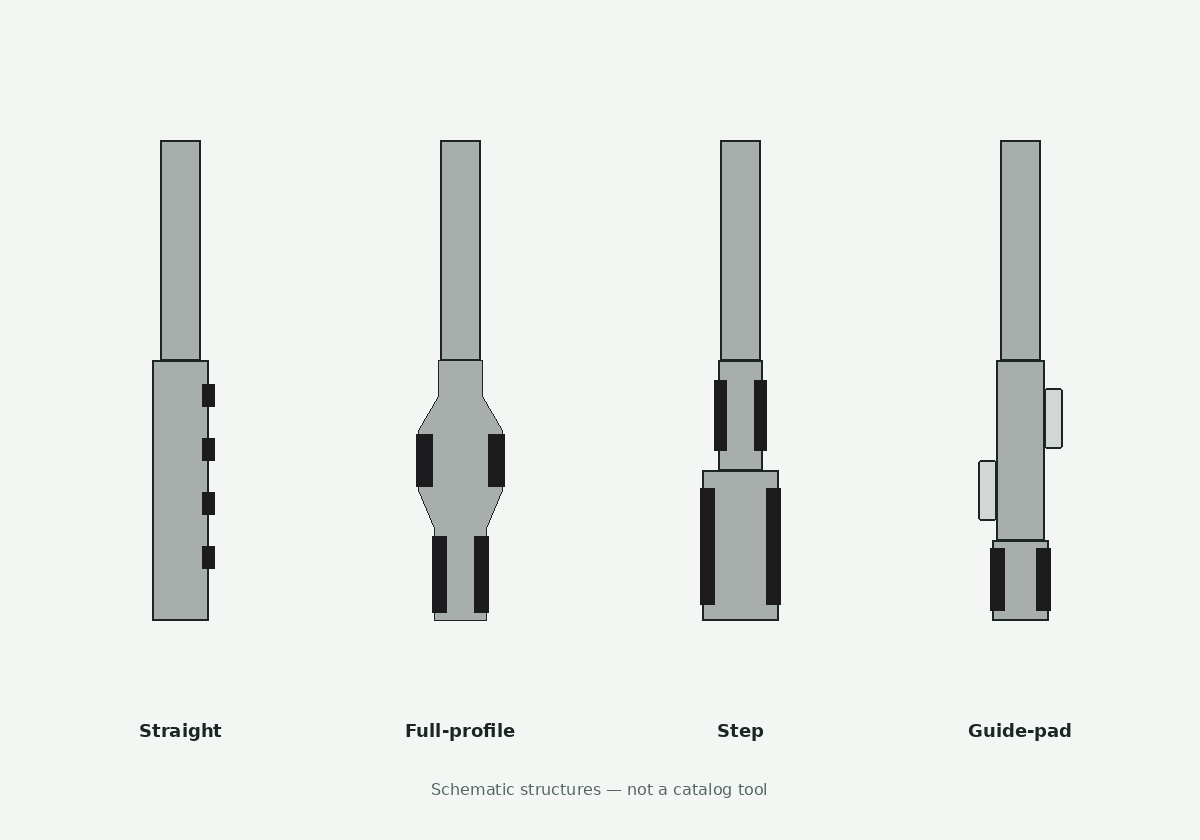
Choosing the structure: full-profile, step, guide-pad or combination
Start from the scrap mode on the part. The simplest structure that holds all the callouts on the print is usually the one to build.
| Structure | Controls | Pick it when | Watch |
|---|---|---|---|
| Single-diameter | Size and finish of one bore | The print is a plain finish diameter | Cannot hold a contour |
| Full-profile (form) | A drawn contour and the relationships inside it | Shoulder, taper, radius or seal land must come from one cutting relationship | Wide cutting lands add chip and heat load; regrind must keep the approved profile |
| Step | Separate diameters and lengths on one axis | Steps are distinct and each has its own tolerance or wear rate | Coaxiality between steps |
| Guide-pad | Stability and roundness | Deep bores, long overhang, roundness scrap | Does not replace a missing contour |
| Combination | Making and finishing the hole in one cycle | Tool changes cost more than the added risk | Chip packing in deep blind holes |
A full-profile reamer earns its cost when split operations keep leaving a mismatch where two tools meet, and the volume justifies freezing the profile after written acceptance. When different diameters wear at different rates, a step design or separate tools share the load better. Piloted designs guide from an existing bore when there is enough entry length, and guide pads need their engagement length, lubrication and preset responsibility written down.
Incomplete contour dimensions are a common cause of revision loops on form and step tools, so send each segment with its tolerance. Step and form RFQ details are in Step and Form PCD Reamer RFQ: What to Call Out per Step.
Materials: where PCD reaming fits
| Workpiece | Direction | Confirm on the RFQ |
|---|---|---|
| Wrought aluminum | Sharp PCD edges, with geometry and coolant set against built-up edge and burrs | Temper, incoming bore, burr limit |
| High-silicon cast aluminum (e.g. ADC12, A380) | Wear-resistant PCD grade, prepared edge, polished chip faces where useful | Silicon content, casting skin, porosity, batch variation |
| Copper, brass and other non-ferrous alloys | Geometry chosen for surface and burr control | Exact alloy, ductility, chip form |
| CFRP and abrasive composites | Dedicated design around entry and exit damage and dust extraction | Laminate stack, fiber direction, delamination limit |
| Steel, cast iron, stainless | Carbide, cermet or PcBN tooling instead of PCD | Send the drawing; we route it to the right tool |
Diamond reacts with iron at cutting temperature, which is why ferrous bores go to other cutting materials. For the full comparison, read PCD reamer vs carbide reamer.
What decides the finished bore
Seven inputs set the bore you measure: the bore requirement, the incoming hole, reamer geometry, holder and runout, machine and fixture, coolant and chips, and the measurement method. The reamer is only one of the seven, so we set tolerance and finish targets with your data and confirm them on the sample. We do not quote a bore tolerance from the tool drawing alone. How PCD reamers control hole accuracy and surface finish covers each input in turn.
Coolant and chips
Through holes let chips run ahead of the tool, blind holes have to carry them back up the flutes, and cross holes add burrs where the bores meet. We place the outlets and size the flute space for your bore and coolant route, and for MQL we confirm the lubricant path against your machine. The tool-side changes for MQL are covered in MQL drilling and reaming: what changes in the tool.

Documented application: ADC12 CVT valve-body bores

Anonymized production record from an HENTRY customer project.
- Upper and lower CVT valve bodies in ADC12 die-cast aluminum
- Nine PCD reamers across the spool-bore family
- Horizontal machining center; spindle runout recorded within the site requirement
- Hydraulic fixture with air checking, recorded as operating normally
- Finished-bore tolerance band recorded as 0.012 mm
Problem. Early production checks found the bores cutting below the tool design diameters: 0.005 mm on average across the family, and 0.007 mm on three H1/H2 bores. That used up most of the adjustment margin.
Correction. We compared the measured bore data with the tool dimensions and changed diameters feature by feature: +0.004 mm on the upper-body H1 and lower-body H1/H2 tools, +0.002 mm on the other six. Cutting parameters were then refined and the bores rechecked on a Hommel combined measuring system.
Result. The revised reamers met the customer's process requirement and were released for production. Shrinkage fell by about 0.002–0.003 mm, depending on the bore. Individual tool life went from 10,000–20,000 parts before optimization to 25,000–30,000 parts after, depending on the tool. These figures belong to this project and its machine, fixture, tool family and measurement method. They are not a commitment for another part. Customer identity and drawings stay confidential.

From drawing to repeat supply
| Step | What happens | What you approve or receive |
|---|---|---|
| 1. Application review | We check drawing, material, feature, incoming hole, machine, holder, coolant, current result and gauge method | A question list if data is missing |
| 2. Concept and risk review | Flute, guidance, body, interface and coolant options compared; open risks named | A proposed concept |
| 3. Drawing approval | Critical diameters, geometry, inspection points and revision frozen | Tool drawing for your sign-off |
| 4. Manufacture and inspect | Body and PCD edges made, then checked against the drawing | Inspection record |
| 5. Sample validation | Bore size, finish, burrs and wear tracked on your part under agreed conditions | A sample plan, proposed for your approval |
| 6. Correct and re-test | Any tool, program or setup change recorded against its revision | Updated record |
| 7. Release | Validated specification, inspection method and application range approved | Repeat-order reference |
| 8. Lifecycle | Repeat supply, returned-tool condition and regrind decisions tracked | Service history per tool |
What we check before a tool ships
- Tool drawing and revision identifier
- Cutting diameters, step lengths and profile
- PCD edges and brazed pockets
- Runout or concentricity, where the control plan includes it
- Coolant passages and outlets
- Preset data, when it is in the agreed scope
- Batch, serial or traceability data the project requires
A tool inspection record does not replace validation on the part. Acceptance still depends on your machine, holder, fixture, coolant and gauge. Plant and inspection records are on manufacturing and quality evidence.

Cost per acceptable hole
The tool price is one line in the comparison. Add new tools, reconditioning, changeover labor, downtime, post-change inspection and scrap, then divide by the holes accepted over the tool's life. The method is worked through in cost per accepted hole: PCD vs carbide reamers.
Regrind and re-tip
When the edge wears, send the tool back. We inspect the remaining PCD, body, pockets and diameter allowance before proposing regrind, re-tip or replacement, and after service we requalify diameter, runout, pads and edge against the current approved revision. Return triggers and the requalification checklist are in the PCD reamer regrind and requalify guide.
Custom PCD reamers for distributors and OEM programs
Distributors keep the customer relationship and bring us in for the non-standard bore. The scope can include application review, project-specific quotation, protected specifications, sample planning, revision control and repeat-order coordination. For each project we keep the application reference, approved drawing and version, inspection scope, sample result, change record, and regrind and reorder history.
OEM and private-label projects can set identification, packaging, documentation and inspection scope by written agreement, with a controlled drawing behind each tool. See the distributor tooling program and OEM/ODM cutting tool manufacturing.
What to send with a PCD reamer RFQ
| Group | Send |
|---|---|
| Finished bore | Diameter and limits, depth, roundness, cylindricity, straightness, finish, burr and datum callouts |
| Hole geometry | Through or blind, steps, shoulders, chamfers, cross holes, interruptions, bottom clearance |
| Workpiece | Alloy and condition, silicon content for aluminum, cast or wrought |
| Incoming hole | How it is made, diameter range, position, stock left, current failure mode |
| Machine and holder | Spindle interface, holder type, overhang, measured runout, fixture |
| Coolant | Internal or external, pressure, flow, filtration, MQL |
| Production | Annual volume, holes per part, current accepted life, target timing |
| Inspection and scope | Gauge method, acceptance plan, documents, sample quantity, NDA |
PCD Reamer Frequently Asked Questions
What is a PCD reamer?
A PCD reamer is a precision finishing tool that uses polycrystalline diamond (PCD)—diamond particles sintered with a binder on a carbide substrate—to size and finish a prepared hole; in this context PCD does not mean pitch circle diameter or other non-tooling acronyms. It removes a controlled allowance, and its geometry, guidance, coolant and inspection scope are chosen from the component and production process.
Do you keep PCD reamers in stock?
No. HENTRY PCD reamers are made to order. Work starts with a review of your drawing and process data, and we build to a tool design you approve. Typical sample lead time is about three weeks; timing depends on tool complexity, material availability, coating schedule and validation requirements.
Can HENTRY design a PCD reamer from my drawing?
Yes. We design and manufacture custom PCD reamers from the component print and process notes: diameters and tolerances, lengths, interruptions, material, incoming hole, machine and holder, coolant, acceptance method and annual volume. Send them through the engineering RFQ and we reply with a proposed design.
What do I send for a manufacturer / distributor RFQ?
Send the bore job. Five things cover most quotes: the drawing with its revision and the bores in scope; the material, with silicon content for aluminum; how the pre-hole is made and how much stock is left; the machine, holder, overhang, measured runout and coolant route; and volume, gauge method, current failure mode and whether you need a sample.
Which materials are suitable for PCD reaming?
Wrought aluminum, high-silicon cast aluminum, copper, brass and selected abrasive composites. High-silicon aluminum is a common PCD job when abrasive wear limits carbide, but silicon content, inclusions, interruptions and coolant still decide the edge design, so we check the alloy and wear mode first. Steel, cast iron and stainless normally need carbide, cermet or PcBN.
How is a PCD reamer different from a carbide reamer?
PCD resists abrasive wear and holds its edge in suitable non-ferrous materials, which helps where size drift or frequent tool changes cause scrap. Carbide works across more materials and is often the better choice for ferrous parts, changing prints or low volumes. Compare the two on cost per acceptable hole: tools, changes, downtime, inspection and scrap, divided by accepted holes.
When should I choose full-profile vs step vs guide-pad vs combination?
Choose full-profile when a continuous contour, such as a shoulder, taper, radius or seal land, has to come from one cutting relationship. Choose step when diameters and lengths split cleanly. Choose guide pads or a pilot when stability or roundness is the scrap mode and the bore offers a guiding feature. Choose combination when drilling and finishing in one cycle is the real question. If unsure, send the print and the scrap mode.
What tolerance and surface finish can a PCD reamer achieve?
No single catalog tolerance or Ra applies to all PCD reamers. Size, roundness and finish depend on pre-hole quality, reaming allowance, assembled runout, machine and fixture, coolant and the gauge method. Too much stock raises force and chip volume; too little leaves rubbing and incomplete cleanup. We write the acceptance criteria on the tool drawing and confirm them in sample validation.
How is a custom PCD reamer inspected and validated?
Tool inspection checks the drawing-defined geometry, edge condition, runout and coolant features before release. Sample validation then checks the finished part under agreed conditions. Batch-to-batch consistency comes from controlled blanks, inspection sampling and revision control, and results are recorded against the specific tool revision, including after regrind.
Can a PCD reamer be reground?
Often yes, when enough PCD remains and the body, pockets, diameter allowance and approved revision support regrind or re-tipping. We inspect the returned tool before proposing a route, requalify it after service and tie the service record to the controlled specification.
Request an engineering review
If you want to prove a design on your part first, we can propose a trial under our sample validation process. If the incoming hole is the problem, start with the PCD drill that makes it. When you are ready, send the drawing and process data through the custom cutting tool RFQ, and we reply with a proposed reamer design for your approval.
Page owner: Kevin Zeng, CEO