
Product Detail
Forming Taps
Forming taps for chipless internal threading in suitable ductile materials. Compare hole and lubrication requirements, then confirm the tool specification for your application.
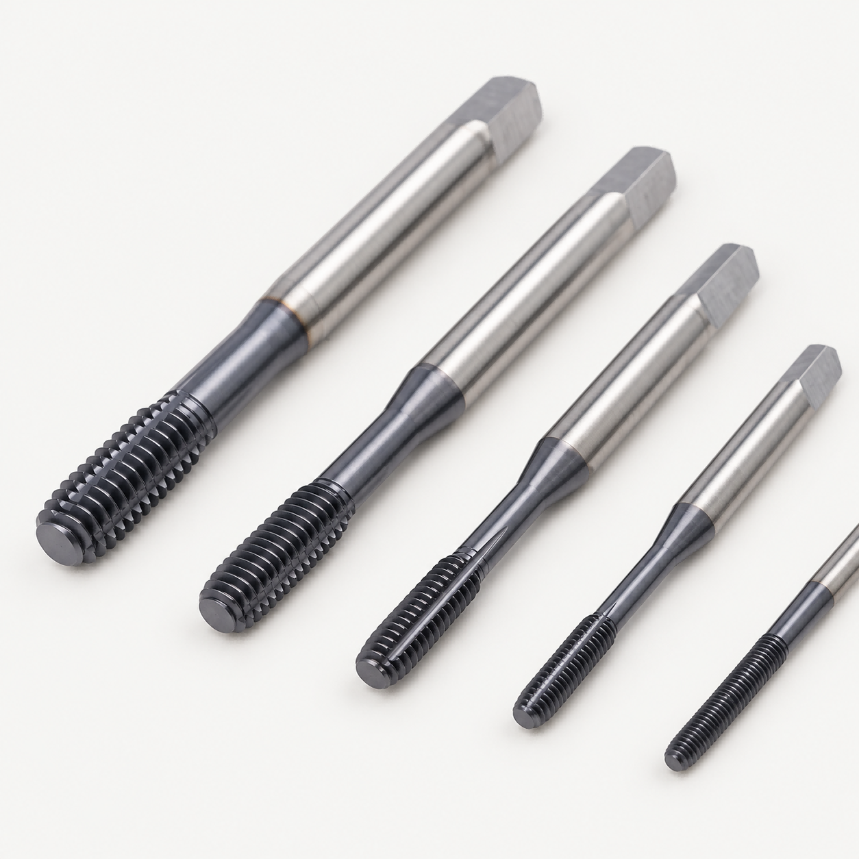
Forming taps create internal threads by displacing material rather than cutting chips. Start with a formable workpiece, a controlled pre-hole and suitable lubrication. [1] [2]
01 / Configuration
Choose the forming route before the tool configuration
Through-hole threads
Confirm the forming lead, exit clearance, thread length and lubricant route before defining the tool.
Blind-hole threads
Specify full thread depth separately from drilled depth. Allow space for the tool lead and bottom clearance.
Lubrication arrangement
Review external delivery, lubricant grooves or internal delivery against the actual setup; availability is confirmed in the tool proposal.
| Your application | Candidate route | Confirm before selection |
|---|---|---|
| Formable material; controlled pre-hole; no tapping chips desired | Forming tap | Material condition, hole tolerance, lubrication and tapping capacity |
| Brittle material or forming suitability not established | Assess a cutting tap or thread mill | Do not approve a forming process from the material name alone |
| Chip-producing blind-hole tapping | Compare spiral flute taps | Chip return path, depth and bottom clearance |
| Several thread requirements or a different CNC process needed | Compare thread milling | Machine capability, tool access and thread standard |
Blind and through-hole forming are both possible; a family label alone does not establish a suitable grade or configuration. OSG tap-family guidance. Compare spiral flute taps, spiral point taps and thread mills.
02 / Why consider forming?
A chipless route with specific process requirements
No tapping chips
The forming operation displaces material. Pre-hole drilling still produces chips that must be removed before tapping. [2]
One process for either hole type
Review blind or through-hole requirements without selecting a cutting-chip evacuation direction. Lead and clearance remain important. [1]
A measurable setup
Record pre-hole size, thread gauge results and the approved lubricant condition so repeat runs can be compared.
03 / Specification
Define a quote-ready forming tap specification
Use the drawing and the proposed tool data sheet to confirm the fields below. Thread size examples are designation formats, not a statement of stocked models or a standard size range.
| Specification field | What to provide | What to confirm in the proposal |
|---|---|---|
| Thread designation | Standard, nominal size, pitch or TPI, thread hand and tolerance class | Exact callout and tap limit; for example, M × pitch or a complete UNC/UNF designation |
| Thread and hole depth | Full usable thread depth and drilled depth, separately | Forming lead, bottom or exit clearance and working reach |
| Tool dimensions | Required shank, square drive, overall length and access envelope | Dimensioned tool drawing with units and revision |
| Pre-hole | Measured diameter, tolerance, roundness and preparation method | Forming-specific approved diameter and control limits |
| Construction | Required substrate and lubricant delivery arrangement | Substrate, surface treatment, grooves and coolant configuration |
| Supply and acceptance | Quantity, repeat-order reference and inspection needs | Proposed model or custom drawing, acceptance criteria and commercial scope |
A DIN dimensional reference does not replace the complete thread designation. Special thread forms and construction requests require confirmation; no universal diameter, hardness or coating range is implied.
Need a dimensional sheet or size list?
Send the thread designation and material to request the applicable forming-tap specification. Use the approved model sheet for dimensions and pre-hole requirements.
Request specification & size list04 / Custom requirements
Build the proposal around your drawing
Feature & access
Thread standard, full depth, entry condition, wall thickness, adjacent features and tool access. Attach the component drawing and revision.
Process & supply
Material grade and condition, current pre-hole, machine and holder, lubricant, quantity and acceptance method. Identify any required tool construction.
A request for solid carbide, special reach or internal coolant is an engineering input, not confirmation of a standard available option. Compare the separately defined solid carbide tap range when construction is your primary selection task.
05 / Material fit
Check formability, substrate and coating separately
| Workpiece / requirement | Coating or surface treatment | Substrate & forming geometry | Selection check |
|---|---|---|---|
| Aluminum or copper-alloy workpieces | Select against adhesion and lubricant compatibility | Confirm grade, condition and proposed forming profile | Do not assume all cast or free-machining grades behave alike |
| Steel or stainless workpieces | Confirm against actual friction, temperature and lubricant conditions | Match the tool construction to the application | Provide exact grade, hardness and tapping setup |
| Brittle, hardened or unfamiliar material | A coating cannot establish workpiece formability | Assess whether forming is appropriate at all | Compare a cutting route if material displacement is unsuitable |
| Specified tool substrate or coating | Name the required treatment; avoid selecting by color | Confirm substrate and profile on the model sheet | Do not infer carbide, coating chemistry or hardness limits from an image |
Formability is a prerequisite, not a universal material-family approval. [1] Tool materials and lubrication configurations are separate choices in manufacturer guidance. [2]
What does a lubricant groove tell me?
A forming tap may have lubricant grooves even though it does not cut chips. Confirm their function from the tool drawing; do not identify a forming tap from flute count or surface color alone. [2]
06 / Speed & feed
Synchronize tapping feed with the thread lead
Use application-approved speed data for the selected tool, material and lubricant. The relationships below convert chosen inputs; they do not select a suitable forming speed.
Spindle speed
n = 1000 × Vc / (π × D)
n: rpm; Vc: peripheral speed in m/min; D: nominal thread diameter in mm. Use a consistent diameter basis from the tool data.
Axial tapping feed
vf = n × L
vf: mm/min; L: thread lead in mm/revolution. For a single-start thread, lead equals pitch. This is not milling feed per tooth. [2]
Confirm feed-per-minute versus feed-per-revolution mode, thread hand and machine-specific synchronization before running. [6] Multi-start threads require the correct lead; do not substitute pitch automatically.
| Input group | Record before trial | Acceptance question |
|---|---|---|
| Tool & workpiece | Tool identifier, drawing revision, material and condition | Does the selected configuration match the job? |
| Pre-hole & lubrication | Measured hole distribution; lubricant type and agreed control method | Is the forming process being supplied consistently? |
| Machine & program | Speed, feed basis, lead, holder, reach and programmed depth | Are synchronization, clearance and torque capacity suitable? |
| Trial result | Thread gauge result, minor diameter where required, surface and tool condition | What evidence permits release or calls for a change? |
07 / Acceptance
Check the tool, pre-hole and finished thread

Confirm the manufacturing route
Use the proposed tool drawing to agree on the substrate, forming profile, lead, shank and lubricant features.
The workshop view shows the manufacturing environment; it is not a record of a specific forming-tap batch.

Agree on inspection outputs
Specify which tool dimensions and thread features must be checked, the inspection method and the document required for acceptance.
Equipment capability does not establish the finished thread result. Validate the trial workpiece against its drawing.
Keep tool inspection separate from workpiece acceptance. Agree on the inspection scope before ordering, then link the trial record to the tool and drawing revision.
| Inspection stage | What to check | Record / output |
|---|---|---|
| Tool specification | Thread callout, forming lead, shank and overall dimensions | Approved model sheet or tool drawing |
| Setup | Holder condition, alignment, actual pre-hole and lubricant delivery | Setup and pre-hole measurements |
| Finished thread | Specified thread gauge result, full depth and minor diameter where required | First-off thread acceptance record |
| Production review | Surface changes, load trend, wear and gauge results at agreed intervals | Batch record and defined tool-change criterion |
A tool photo or equipment photo is not a product inspection report. Ask for the inspection documentation relevant to your project. See manufacturing and quality evidence and the sample validation process.
08 / Troubleshooting
Form tapping problems and checks
Thread crest appears overformed
Possible causes: The pre-hole may be below the approved size.
Solution to assess: Measure actual hole sizes before changing the forming tap.
Validate: Compare trial threads after restoring the approved pre-hole window. [3]
Rough thread surface or material pickup
Possible causes: Adhesion or insufficient effective lubrication may be involved.
Solution to assess: Inspect the tool and lubricant condition; review fluid suitability with the supplier.
Validate: Check the next trial’s surface and gauge results under recorded conditions. [4]
Tap breaks during the cycle
Possible causes: An undersize pre-hole, inadequate lubrication or unsuitable clamping may contribute.
Solution to assess: Stop the process; inspect hole, tool, holder and delivery conditions before restarting.
Validate: Repeat a controlled first-off trial after identifying the cause. [5]
Results change between batches
Possible causes: Pre-hole or lubricant variation is a candidate to check, not a diagnosis.
Solution to assess: Compare current measurements and setup records with the approved trial.
Validate: Check one controlled change at a time; retain traceable thread acceptance results. [2]
09 / Application validation
Define the trial before committing to repeat supply
Application baseline
Record the actual thread, material condition, pre-hole distribution, setup and acceptance requirements.
Controlled proposal
Identify the proposed forming tap, dimensions, lubricant arrangement and trial conditions.
Release decision
Review measured thread results and tool condition. Approve the documented specification only for the validated scope.
Use the agreed trial results and acceptance record to define the scope of repeat supply.
10 / Questions
Forming tap questions
Can forming taps be used in blind holes?
Yes, when the material and tool are suitable. Confirm full thread depth, forming lead, bottom clearance and lubricant access; a chipless process does not remove the need for clearance. [1]
Can I use the drill size specified for a cutting tap?
No. Use the selected forming tap’s approved pre-hole diameter and tolerance for the workpiece. Do not substitute a cutting-tap drill chart. [2]
Does “forming tap” mean solid carbide?
No. Forming describes the process. Tool substrate, coating, groove arrangement and dimensions are separate specification fields to confirm in the proposal.
Will a forming tap work in every aluminum or steel grade?
No. Suitability depends on the grade, condition and formability. Send the exact material and hardness; assess brittle or uncertain materials before selecting a forming route. [1]
Do lubricant grooves remove chips?
Their role is lubricant delivery, not cutting-chip evacuation. Confirm the groove and coolant arrangement for the hole depth, orientation and process. [2]
What should I send for a quotation?
Send the complete thread callout, material, full thread depth, pre-hole data, machine and holder, lubrication, quantity and drawing revision. Ask for the proposed tool specification before approving supply.
Technical basis
References & related tools
- OSG — tap families
Scope of reference
Forming taps for suitable ductile workpieces and blind / through-hole applications.
- Gühring — fluteless tapping
Scope of reference
Process, lubrication, substrate distinctions, pre-hole sensitivity and pitch-synchronized advance. Manufacturer-specific product results are not HC specifications.
- Gühring — overformed threads
Scope of reference
Undersize pre-hole as a possible cause; use the correct forming-tap hole requirement.
- Gühring — thread surface
Scope of reference
Cold welding and lubricant condition as checks for poor thread surfaces.
- Gühring — tool breakage
Scope of reference
Checks involving hole size, lubrication and clamping.
- Haas — tapping cycle and feed relationship
Scope of reference
Haas mill example relates tapping feed to spindle speed and thread pitch. Verify your own machine, control version and feed mode; this page supplies no ready-to-run program.
Technical references explain process principles; they do not establish HC stock, coating, dimensions or performance.
Drawing-based enquiry
Request a forming tap proposal
Include the thread callout, material, full thread depth, pre-hole, quantity and drawing. Add machine, holder and lubrication details when available.