
Product Detail
Spiral Point Taps
Spiral point taps for through-hole threading with forward chip evacuation. Compare tap types, confirm exit clearance, and define the thread, material and tool specification.
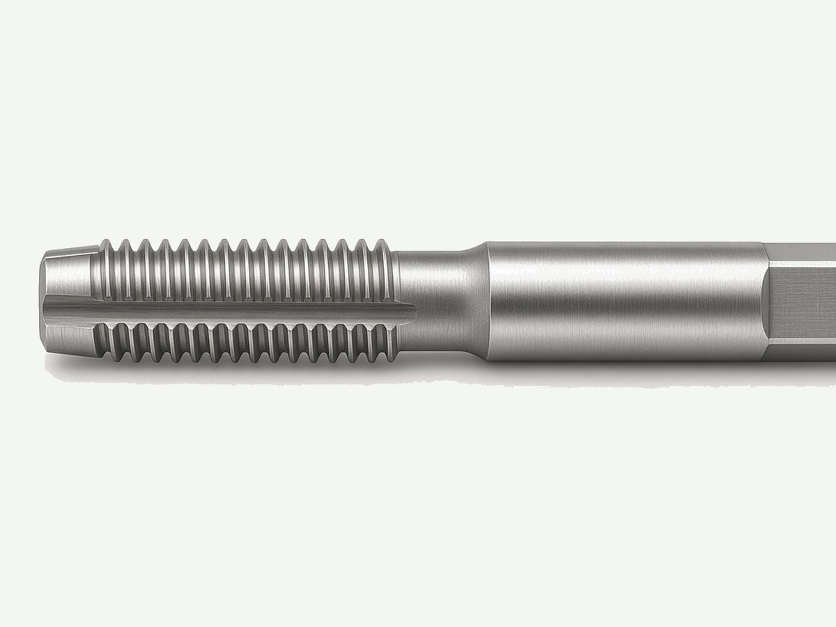
Spiral point taps, also called gun taps, cut internal threads and direct chips ahead of the tool. Review the through-hole exit and fixture space before selecting the tap. [1] [2]
01 / Select the chip route
Match the tap to the hole and chip exit
Spiral point tap
Consider for through-hole cutting when chips can travel ahead and leave the exit. Confirm space beyond the component. [2]
Spiral flute tap
Compare when chips must return toward the shank, especially for blind-hole work. [1]
Forming tap
Consider a separate chipless process only when workpiece formability, pre-hole and lubrication are suitable. [1]
| Machining condition | Candidate | Check before approval |
|---|---|---|
| Open through hole in a material producing continuous chips | Spiral point tap | Exit clearance, lead length, chip path and fluid |
| Blind hole or obstructed forward chip route | Assess spiral flute or another route | Full depth, chip removal and bottom clearance |
| Suitable ductile workpiece and a chipless requirement | Assess forming tap | Forming-specific hole size and material condition |
| Interrupted, cross-drilled or uncertain feature | Application review first | Provide the complete feature drawing; a through-hole label is not enough |
A spiral point tap can have straight main flutes. The angled point geometry, not a helical flute along the body, drives chips forward. [3] Compare spiral flute taps, straight flute taps and forming taps.
02 / Process advantages
Use forward chip flow where the exit is open
Keep the chip path ahead of the cutting zone
Spiral-point geometry sends cutting chips through the far side of a suitable through hole. It changes the chip route; it does not guarantee freedom from packing. [2]
Review component thickness, tapping travel, nearby features and fixture clearance together before confirming a configuration.
Chip-route selection
Compare a forward-ejecting route with pulling long chips back through the thread. Choose against actual chip behavior. [2]
Lead matched to the feature
Select chamfer and cutting length from the hole and material requirements rather than copying another tap’s geometry. [3]
Controlled repeat setup
Retain the tool drawing, pre-hole checks, program basis and acceptance record so changes can be traced.
03 / Specification
Confirm the thread, cutting lead and working envelope
Use the proposed model sheet or custom drawing to agree on the specification. The fields below are quotation inputs, not a stock-size list.
| Specification | Customer input | Proposal check |
|---|---|---|
| Thread | Standard, nominal size, pitch or TPI, hand and tolerance class | Complete thread callout and appropriate tap limit |
| Depth & thickness | Full thread depth and through-hole thickness separately | Cutting lead, threaded length, tapping travel and exit allowance |
| Working envelope | Overall length, neck or reach, shank and square drive | Dimensioned drawing and tool-holder compatibility |
| Pre-hole | Diameter, tolerance, preparation and measured condition | Approved cutting-tap hole requirement; do not use forming-tap sizes |
| Construction | Requested substrate, surface treatment and coolant arrangement | Proposed material, coating, flute and point geometry |
| Supply & acceptance | Quantity, drawing revision and inspection needs | Model or custom identifier, inspection scope and order conditions |
Request the matching dimensional sheet
Send your thread designation and material to obtain the relevant specification and confirm available sizes. Use the agreed drawing for dimensions, not a product photograph.
Request specification & size list04 / Drawing-based requirements
Describe the part and the space beyond it
Thread & tool access
Provide the thread callout, full depth, entry condition, wall thickness, any cross holes and the fixture arrangement beyond the exit.
Machine & supply scope
Add machine, holder, fluid, current drill and tap, existing problem, quantity and inspection requirements. Specify any substrate or special-reach requirement.
A request for solid carbide, internal coolant or a special thread form requires construction confirmation. The spiral-point family name does not establish a universal substrate, hardness limit or size range. Compare solid carbide taps when construction is the primary requirement.
05 / Material & construction
Select material fit separately from chip direction
| Workpiece / task | Coating or treatment | Substrate & geometry | Selection check |
|---|---|---|---|
| Steel through-hole threading | Select from the proposed series and actual fluid | Confirm substrate, edge preparation and spiral point | Material grade, condition, pre-hole and chip behavior |
| Stainless steel through-hole threading | Confirm against adhesion and application conditions | Assess material-specific geometry and holder setup | Hardness, drilling condition, fluid and measured trial results |
| Aluminum or copper-alloy components | Specify treatment without inferring it from color | Match the proposed profile to the exact grade | Chip shape, built-up edge, exit space and acceptance needs |
| Brittle or short-chipping material | Do not assume the same coated tool fits | Compare straight flute or another approved design | Material and chip behavior may change the preferred family |
Manufacturer guidance selects by workpiece, thread form and hole type. [3] Material-family names do not confirm an HC model, coating chemistry or operating window.
06 / Speed & feed
Use the approved tapping speed and synchronized feed
Confirm a starting speed for the proposed tool, workpiece and fluid. The equations convert inputs already selected for the application; they are not universal cutting recommendations.
Spindle speed
n = 1000 × Vc / (π × D)
n: rpm; Vc: m/min; D: nominal thread diameter in mm. Keep the diameter and unit basis consistent with the tool data.
Axial tapping feed
vf = n × L
vf: mm/min; L: thread lead in mm/revolution. For a single-start thread, lead equals pitch; use the actual lead for multi-start threads. [6]
Check the machine’s feed-per-minute or feed-per-revolution mode and tapping synchronization. Do not transfer floating-holder underfeed guidance into a rigid synchronous cycle. [4] [6]
| Record | Required input | First-off check |
|---|---|---|
| Tool & material | Tool identifier, revision, thread and actual workpiece condition | Correct family and material-specific proposal |
| Pre-hole & exit | Measured hole size, thickness and clear chip path | No packing against a shoulder, fixture or nearby part |
| Program & setup | Speed, feed basis, lead, holder, reach and fluid route | Synchronized advance/reversal and adequate travel |
| Workpiece result | Thread gauge, full depth, exit burr and surface requirements | Accepted thread and a defined inspection interval |
07 / Inspection
Check the tool, exit and finished thread

Specify the tool inspection
Agree on thread identity, point and chamfer configuration, shank dimensions, cutting-edge condition and the document required for acceptance.
A workshop photograph shows the environment; it does not establish the result for a particular tool batch.

Validate the assembled process
Record holder and setup checks, pre-hole measurements, thread gauging, full usable depth, exit condition and the selected tool-change criterion.
Link the first-off result to the program, tool and component drawing revision.
| Stage | What to check | Evidence |
|---|---|---|
| Tool | Callout, lead, key dimensions and edge condition | Agreed tool inspection record |
| Setup | Pre-hole, alignment, holder, chip exit and fluid | Setup and measured hole record |
| First-off part | Specified gauge result, usable depth, surface and exit burr | Drawing-based thread acceptance |
| Repeat production | Wear, gauge results and chip accumulation | Batch checks and revision control |
Review manufacturing and quality evidence and the sample validation process.
08 / Troubleshooting
Through-hole tapping problems and checks
Chips pack at the exit
Possible causes: The forward path may be obstructed or the selected tap may not suit the chip behavior.
Solution to assess: Inspect the hole exit, nearby fixture and accumulated chips before restarting.
Validate: Observe chip release and recheck thread quality in a controlled trial. [2]
Cutting lead chips or the tap breaks
Possible causes: Trapped chips, an undersize drill hole, wear or inadequate lubrication may contribute.
Solution to assess: Stop and inspect the failed tool, actual hole, clearance and fluid delivery.
Validate: Restart only after the cause is addressed and first-off results pass. [5]
Thread gauges oversized or undersized
Possible causes: Tap limit, wear, pre-hole and feed/holder behavior are candidates to check.
Solution to assess: Verify the correct gauge and callout; measure the hole and compare with the approved setup.
Validate: Confirm the thread across the required depth; do not compensate blindly. [5]
Material sticks to the cutting edge
Possible causes: Tool wear, inappropriate application selection or lubrication may contribute.
Solution to assess: Inspect the edge and actual fluid condition; review tool and treatment selection.
Validate: Compare surface, gauge result and wear after one controlled change. [5]
Wear increases unexpectedly
Possible causes: Speed, lubricant, tool choice or pre-hole surface condition may differ.
Solution to assess: Compare current records with the approved trial before increasing speed or changing coating.
Validate: Track thread acceptance and edge condition against a defined limit. [5]
Results change after setup or fixture changes
Possible causes: Clamping, synchronization, reach or the exit path may have changed.
Solution to assess: Recheck the complete setup rather than treating it as the same application.
Validate: Repeat the first-off acceptance and retain the changed setup record. [4]
09 / Application validation
Approve a through-hole trial with traceable conditions
Baseline
Capture thread, material, pre-hole, thickness, exit clearance and the current issue.
Controlled trial
Record the proposed tool, program basis, holder, fluid and agreed inspection method.
Release scope
Use actual thread results and tool condition to approve the specification for repeat supply.
Agree on the sample size and acceptance plan for the project. A first-off pass is not a tool-life result or a guarantee for other setups.
10 / Questions
Spiral point tap questions
Are spiral point taps intended for through holes?
Yes. Their point directs chips forward, making an open exit a central selection condition. Check the workpiece underside and fixture space as well as the hole itself. [1] [2]
Is a spiral point tap the same as a spiral flute tap?
No. Spiral point geometry drives chips ahead of the tool; spiral flutes are used to pull chips back toward the shank. Select from the required chip route, not the word “spiral.” [2]
Can I use one in a blind hole?
Do not treat it as the default blind-hole solution. The forward chip path needs space. Compare a spiral flute tap or another approved process when chips cannot leave forward. [1]
Does the straight main flute make it a straight flute tap?
Not necessarily. A spiral point tap can have straight main flutes; the chip-driving point is the distinguishing feature. Verify the lead geometry from the tool drawing. [3]
Are HSS-E, carbide and coatings interchangeable?
No. The tool family describes chip direction, not a single substrate or coating. Confirm the proposed construction for your material and setup; do not infer it from surface color.
What information is needed to choose a tap?
Provide the thread standard, size, pitch and class, material and hardness, full thread depth, through-hole thickness, exit clearance, pre-hole, machine, holder, fluid and quantity.
Technical basis
References & related tools
- OSG — tap-family selection
Scope of reference
Spiral point taps for through holes; spiral flute and forming tap distinctions.
- YAMAWA — spiral pointed taps for through holes
Scope of reference
Forward chip direction and comparison with spiral flute taps. Listed YAMAWA models are not HC specifications.
- Sandvik — choosing tap type and chamfer
Scope of reference
Hole, material, thread callout and chamfer selection. Manufacturer-specific ranges are not transferred.
- Sandvik — tapping operation tips
Scope of reference
Clamping, pre-hole, fluid delivery and feed setup. Attachment-specific guidance is not a universal rigid-tapping rule.
- Sandvik — tapping troubleshooting
Scope of reference
Possible causes of chipping, breakage, wear and thread-size problems; diagnosis requires actual measurements.
- Haas — tapping feed relationship
Scope of reference
Machine-specific example relating spindle speed and feed to thread pitch. Confirm the actual control and units; no runnable program is supplied.
References explain selection and process principles; they do not establish HC stock, tool dimensions, coating or measured results.
Drawing-based enquiry
Request a spiral point tap proposal
Send thread, material, full thread depth, through-hole thickness, exit clearance and quantity. Attach the drawing and current tooling details.