
The line is moving to MQL. The drill and the PCD reamer that ran well on flood or through-tool emulsion are on the bench, the trial date is set, and someone has to say whether those exact tools can go straight onto the new system. If they can't, the channels, the exits, the flute finish, or the holder interface has to change first. Get that call wrong and the trial fails for a delivery reason, and the plant writes down "MQL doesn't work on this hole" when the problem was really the tool.
MQL replaces a coolant flood with a small amount of oil carried in compressed air, and that oil has to reach the cutting edge through the spindle, the holder, and the tool. This makes four things part of the tool specification: the type of MQL system (single- or dual-channel), the channel section and exit position, the flute surface, and a sealed path from holder to tool. Some holes should not be switched without a trial at all. This page goes through each of these and ends with the MQL fields to put in an RFQ. Whether a hole needs delivery through the tool in the first place is a separate decision, covered in when through-coolant is required on solid carbide drills. This page starts after that decision, at the point where the medium changes from liquid to aerosol.
An MQL drill or reamer has to carry a small oil-air aerosol to the cutting edge instead of a coolant flood. That makes the MQL system type (single or dual channel), the coolant channel section and exit position, the flute surface, and a sealed holder path part of the tool specification. Some deep or blind holes need a trial before switching.
Single-Channel vs Dual-Channel MQL: What It Means for the Tool
The system type decides how much of the delivery work falls on the tool. In a single-channel system the aerosol is made before it enters the machine, so it has a long way to travel to the edge. In a dual-channel system air and oil stay separate until just before the tool, so there is much less path for the aerosol to degrade on. Find out which one the line has before judging any tool.
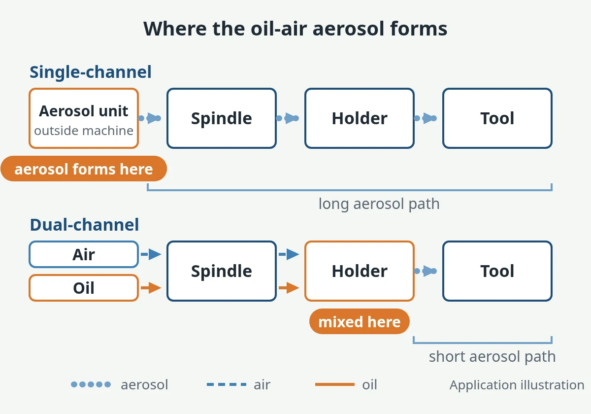
Single-channel. The oil mist is made in an aerosol unit outside the machine, then travels through the spindle, the holder, and the tool to the cut. A study of MQL supply through drill cooling channels (Schumski et al., 2024) lists the drawbacks as the long transport path, the interfaces between components, and the centripetal force from the rotating spindle, holder, and tool. As a result, larger droplets can settle out as a film on the channel walls, and mainly the small droplets reach the cutting zone. For the tool, this means its internal channels are the last and often the narrowest leg of a long path that is already losing oil.
Dual-channel. Air and oil travel separately through the spindle and are brought together just before the holder, where the oil is atomized. The same paper notes that with this layout the effect of transport and spindle rotation can largely be ignored, which is why dual-channel suits high spindle speeds. For the tool, that is more forgiving, but not a free pass. The aerosol still has to cross the holder-to-tool joint and run the full length of the tool's channels without collecting on the walls.
| System | Where the aerosol forms | What it asks of the tool | What to ask the plant |
|---|---|---|---|
| Single-channel | Before the machine, in an external aerosol unit | Channels, transitions and exits that lose as little oil as possible at the end of a long path; sensitivity to spindle speed | Unit type, distance to spindle, typical spindle speed, whether several spindles share one unit |
| Dual-channel | At or just before the holder | Clean holder-to-tool transfer and channels that don't collect oil; the mixing point sits close to the tool inlet, so the joint matters | Where mixing happens (spindle nose or holder), holder type used with it |
| Unknown | — | Nothing can be frozen yet | Ask the machine builder or maintenance and write "unknown" on the RFQ rather than guessing |
What Changes on an MQL Drill or Reamer
A tool built for flood or high-pressure emulsion was built to push liquid volume. Aerosol behaves differently. Oil separates out where the flow turns sharply or the cross-section jumps, it forms a film on channel walls, and it carries away very little heat. A tool that works on emulsion is a good starting point, but it does not prove the tool will work on MQL. Review these items on the tool drawing before the trial:
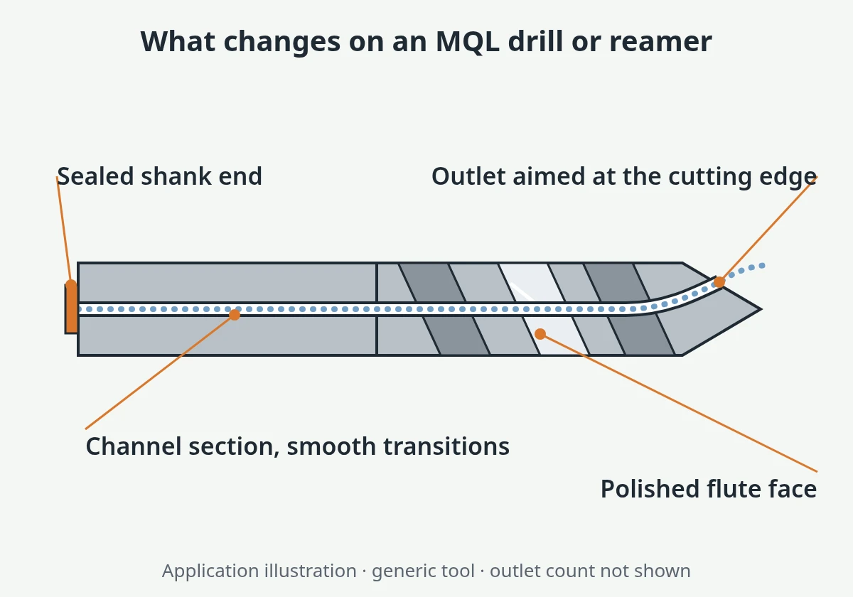
Channel cross-section and count. The same study compared drills with two channel diameters on the same aerosol unit. The larger channel passed more air and more oil at the same settings; the smaller one added internal pressure loss and reduced both. That was one test setup, not a sizing rule. What it shows is that a channel sized for liquid flow is not automatically the right size for aerosol. Check the channel section against the tool diameter and the carbide or body wall left around it, rather than copying the flood version.
Exit position. In the same study the oil left the channel outlets mostly as ligaments rather than as a fine mist. Oil that arrives as ligaments has to leave the outlet close to where it is needed. For a drill, that means outlets on the flank close to the lips. For a reamer, it means outlets that serve the lead or chamfer, where the cutting happens, not outlets that empty into the flute and leave with the chips. Separate research on through-tool MQL drills (Raval et al., 2020) found that channel shape and helix angle change where the mist concentrates as it leaves the outlet. So check the outlet position against the edges each outlet has to serve, not just count the holes.
Internal path. Look for sharp corners, sudden diameter steps, and dead pockets between the shank inlet and the outlets. Each one is a place where oil can separate and collect. Tools with cross-drilled branches or plugged side holes should be reviewed for exactly this. On a combination drill-reamer, the path has to feed every cutting section on the body. That product page covers the combination structure itself. This check covers only how the aerosol gets there.
Flute and chip-contact surface. Without a flood to wash chips out, chips have to slide out along the flute face on their own. A polished flute and chip-contact surface lowers friction and makes it harder for aluminum to stick. Chip form matters more than it does under flood: short, curled chips that leave the hole, not long ribbons that pack. Choosing the point and flute count is covered in flute count and point angle selection. On MQL, check the finish of those surfaces as well as their geometry.
Heat. MQL lubricates but removes little heat, so more of it stays in the chips, the tool, and the holder. Research comparing MQL with flood does not all point one way. Several studies report higher thermal load under MQL. That is why the red-flag list below includes heat-sensitive holes.
MQL PCD Reamer for Aluminum
The clearest published case for MQL reaming is narrow, and it should be read that way. Kurgin et al. (2014) compared single- and dual-channel MQL for reaming spool bores in an automotive aluminum transmission valve body, with through-tool flood coolant as the baseline. With proper tooling and machining parameters, dual-channel MQL performed as well as or better than flood. Single-channel was not considered suitable for that application. That is one study on one part type. It supports trialing dual-channel MQL on similar aluminum spool bores (valve-body spool bore machining). It is not a general rule for every reamed hole, and it shows the system type matters as much as the reamer.
On the reamer itself, check that:
- Outlets sit between the cutting edges and aim at the lead, so each edge gets oil where it starts to cut.
- The chip-contact faces are polished, and there is enough chip space for chips to leave without liquid pushing them.
- Guide pads, if the design has them, get lubrication too. A dry pad rubs the bore it is meant to support.
Aluminum adhesion is the risk to watch when the liquid goes away. PCD reduces the tendency but doesn't remove it. The check sequence is in controlling built-up edge when PCD reaming high-silicon aluminum.
MQL Carbide Drill Coolant Channels
Whether the channels run straight or helical through the blank is a question of drill geometry and blank supply, covered in straight vs helical coolant holes in carbide drills. MQL adds three questions to that choice: whether the channel section suits aerosol rather than liquid, whether the path has abrupt transitions, and whether the outlets on the flank serve both lips evenly. A through-coolant carbide drill that has run well on emulsion is a reasonable place to start the MQL review. Its channels were still sized and aimed for a different medium, so review them before the trial. The same three questions apply to a standard solid carbide drill with internal channels.
The Holder and Spindle Side: Sealing, Adjustment Screw, Interface
On MQL, the joint between holder and tool is part of the tool specification. Aerosol that leaks into the clamping bore, or slows down in an open cavity behind the shank, loses oil before it reaches the channels. Fixing this sometimes means a different shank end on the tool, not just a different holder.
- Sealed path. The aerosol should pass from the holder into the tool inlet with no leak into the clamping area of the holder or into the machine. A common practice is to use a holder made for MQL, which differs from a flood holder in the coolant tube and the length-adjustment screw; single- and dual-channel systems can need different transfer parts.
- Shank end and adjustment screw. Some MQL holders seal against a shaped shank end, so the tool's back end has to seat fully on the adjustment screw. A shank that doesn't fully contact the screw leaves a gap that disturbs the supply. If the holder uses a shaped seat, the shank end form goes on the tool drawing.
- Low dead volume, gradual transitions. Keep the space between the screw and the tool inlet small, and avoid sudden jumps in diameter along the path. For single-channel systems in particular, a common practice is to make the tool's own channels the narrowest point in the system, not a step down after an oversized cavity.
- Spindle interface. The interface (HSK and similar tapers are common examples) and the MQL transfer inside the spindle belong to the machine. Name them on the RFQ so the tool's inlet can be matched to them, and state the holder type (shrink-fit, hydraulic, collet) and whether it is the MQL version.
- Heat at the shank. If the holder runs noticeably warmer on MQL than on flood, first check that the aerosol reaches the outlets (seal and channel path), then compare size at a stable part temperature.
If the current holder and the tool's shank end don't match, XRZ can propose a shank end and inlet form to suit your holder and send it for your approval before the tool is made.
When MQL Is a Red Flag for the Hole
Some holes are poor candidates for MQL whatever tool you use. Others can work, but only after a trial on the actual line. Treat the conditions below as reasons to trial first, not as a verdict. Depth and peck planning for solid carbide are covered in deep-hole carbide drilling: L/D, peck and chip escape.
| Hole condition | Why MQL is at risk | What to do before switching |
|---|---|---|
| Small, deep hole on a single-channel system | A Procedia Manufacturing paper on small-tool deep-hole drilling (tool D < 5 mm, L > 25D) reports that Venturi-based single-channel MQL struggles to produce the required oil quantity as the air-pressure difference drops; its authors propose a bypass design to fix this | Ask the system builder whether the unit can supply that tool; trial on the actual machine; keep the flood route until the trial passes |
| Blind hole where chips must come back up the flutes | Nothing flushes the bottom; chips rely on flute space, chip form and the air stream | Check chip form and flute space first; see below |
| Tight-tolerance bore sensitive to heat | Less heat removal can move size between the first part and later parts, or between flood and MQL | Measure at a stable part temperature; compare against the flood baseline on the same gauge |
| Material that needs heat removal (hardened steel, some stainless grades) | Lubrication alone may not control edge temperature | Trial first; keep through-tool liquid as the fallback |
Blind holes. A blind hole on MQL has no liquid to push chips out of the bottom. If chips already pack on flood, MQL will not fix that. Work through the carbide drill chip-packing checklist before changing the delivery medium.
Heat-limited holes. Where a hole depends on liquid to carry heat and chips away, the decision about through-tool liquid still applies and may point the other way. That decision is on through-coolant carbide drilling when flood coolant is not enough. Cast iron is the case where dry, MQL or coolant is chosen hole by hole; see carbide drilling gray and ductile cast iron.
For any hole on this list, run the switch as a written trial: record a flood baseline first, then run the MQL tool with the same gauge and acceptance list. The steps are in the sample validation process.
MQL Fields to Put in Your RFQ
"Make it MQL" on an RFQ is not a specification. These fields let the toolmaker match channels, exits, flute finish, and shank end to your system. If the hole is one of several on a housing or powertrain print, mark which holes are moving to MQL. Part-family routing is on automotive and EV powertrain machining.
- MQL system type: single- or dual-channel, and the unit make if known. Write "unknown" if nobody has confirmed it.
- Spindle interface, holder type, and whether the holder is the MQL version; the adjustment-screw or shank-end form if the holder needs one
- MQL oil type
- Air pressure and oil setting, if known (your values; leave blank rather than guess)
- Hole diameter and depth, blind or through, cross holes or interruptions
- Workpiece material and condition; silicon content for aluminum
- Tolerance, roundness, and surface requirement for reamed bores
- The current tool and how it performs on flood or through-tool emulsion: size, finish, chip form, wear
- The target: for example, "same size and finish as the flood baseline on the same gauge"
- Spindle speed range and whether several spindles share one MQL unit
- Photos of chips and of the tool's outlets and flutes from the current process
Frequently Asked Questions
Can I use my through-coolant drill with MQL?
Sometimes. A drill with internal channels can carry MQL aerosol, but its channels, outlets, and shank end were designed for liquid. Check the channel section and transitions, whether the outlets serve both lips, and whether the shank seals in your MQL holder. Then run a trial against your flood result before you release it.
What is the difference between single-channel and dual-channel MQL?
In a single-channel system, the oil-air aerosol is made outside the machine and travels through the spindle, holder, and tool, so droplets can settle on the walls and spindle speed has an effect. In a dual-channel system, air and oil travel separately and are mixed just before the tool, which makes it better suited to high spindle speeds. The system type changes how much the tool's own channels have to make up for.
Can PCD reamers run with MQL in aluminum?
They can in suitable applications. A 2014 study on reaming spool bores in an aluminum transmission valve body found that dual-channel MQL matched or beat through-tool flood with proper tooling and parameters, while single-channel was not suitable for that job. That result belongs to that application. For your bore, confirm the system type, outlet position, flute polish, and pad lubrication, then run a trial.
What information does a tool supplier need for an MQL tool?
The MQL system type, spindle interface and holder, oil type, air and oil settings if known, hole diameter and depth, whether it is blind or through, the material, how the current tool performs on flood, and the target result. Mark any unknown field as unknown so the proposal can stay conditional.
Next step
If your line is moving to MQL, tell us which system it runs and send the drawing along with how the current tool performs on flood. We will review the tool against your system and propose the coolant exits, channel path, flute finish, and shank end we would change. You approve the proposal before anything is made, and the result is confirmed in a trial on your machine.