
The part is a valve body, a manifold, a pump housing or a brake component, and the drawing says "cast iron." Before the first hole, someone has to pick a carbide drill and decide how to run it: dry, with MQL, or wet. They also have to decide how to start the hole on an as-cast face with scale and sand on it, and whether the drill that runs well in the gray iron version of the part will survive the ductile version. Look it up and the answers conflict. One guide says gray iron drills fine dry. Another says drilling always needs coolant.
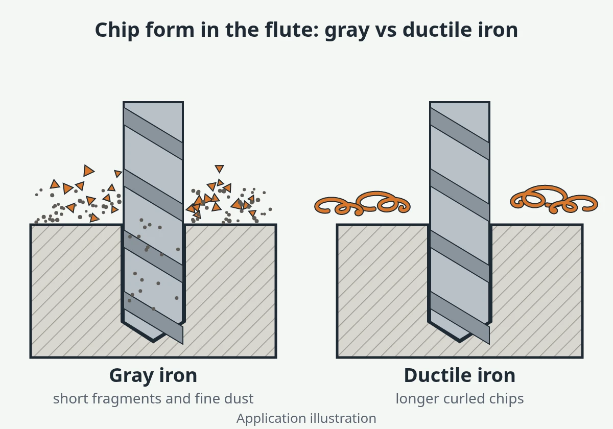
Both can be right, because they are describing different holes. Gray and ductile iron drill differently. Flake graphite breaks the chip into short fragments and dust, and nodular graphite leaves a longer chip, more cutting force and more burr. After the grade, the hole decides the coolant: how deep it is, whether it is blind or through, whether it breaks into a cross hole, and whether the machine can extract dust. The casting skin decides how the hole should start. This page works through those decisions in order and ends with what to send for a drill recommendation. It gives no cutting data.
Carbide drills handle cast iron well, but gray and ductile iron are not the same job. Gray iron's flake graphite breaks chips into short fragments and dust, while ductile iron makes longer chips, more force and more burr. Hole depth, blind or cross holes and dust handling decide whether you drill dry, with MQL or with coolant, and the casting skin decides how to start the hole.
Gray vs Ductile Iron: Why the Same Drill Behaves Differently
Both irons are iron with graphite in them. The difference is the shape of the graphite. In gray iron (EN-GJL, also called grey or flake graphite iron) it forms flakes. The flakes interrupt the metal matrix, so the chip breaks almost as soon as it forms, and the graphite smears onto the cut as a dry lubricant. In ductile iron (EN-GJS, also called nodular or spheroidal graphite iron) the graphite forms round nodules. The matrix around them is continuous and much tougher, so the chip holds together longer and the edge has to do more work to shear it.
| Gray iron (GJL, flake graphite) | Ductile iron (GJS, nodular graphite) | |
|---|---|---|
| Chip form | Short fragments and fine dust | Longer, segmented or curled chips; closer to a short-chipping steel |
| Cutting force and heat at the edge | Lower; graphite helps lubricate | Higher force, a hotter edge |
| Exit condition | If the exit edge crumbles or breaks out, check the breakthrough feed and the outer corners first; burr is usually light | A burr that stays attached at the exit and at intersections |
| Main wear driver | Abrasion, from the graphite-iron dust and hard phases in the matrix | Abrasion plus heat and chip contact |
| What it means for the drill | Chip room is rarely the problem; dust and corner wear are | Chip evacuation, edge strength and exit burr need planning |
Two things matter more than the grade name. The first is the matrix. A pearlitic matrix, or a casting on the harder side of its grade, is more abrasive than a ferritic one, whether the graphite is flakes or nodules. Castings with the same designation can differ from one foundry or pattern to the next, so a hardness reading from the actual parts tells you more than the drawing does. The second is chill. Thin walls, sharp edges and fins cool fastest in the mould and can form hard, carbide-rich spots. A drill that runs quietly through the thick sections can chip its corner at the one hole that starts next to a thin flange.
Compacted graphite iron (CGI, GJV) has graphite between the two shapes, is generally harder to machine than gray iron, and is not covered here.
If the drawing only says "cast iron," confirm the grade from the material certificate before choosing anything. Gray and ductile versions of the same part look the same on the pallet.
Dry, MQL or Coolant for Drilling Cast Iron: Decide by the Hole
The conflicting advice comes from answering the question for "cast iron" as if it were one job. Dry drilling gray iron is reasonable where the chips and dust can leave the hole on their own and the machine can deal with the dust. Coolant or MQL becomes necessary where chips cannot get out, where the drill runs hot, or where hole size has to stay stable. Decide per hole, not per material.
| Hole and setup | Usual starting direction | Why |
|---|---|---|
| Shallow through hole in gray iron, dust extraction at the spindle or enclosure | Dry, often with an air blast (through the tool if the spindle has it) | Short chips and dust fall or blow out of an open hole; no sludge, and the coolant system stays clean |
| Deeper hole, or any blind hole, in gray iron | MQL or through-tool coolant | Dust and fragments collect at the bottom of a blind hole and in the flutes of a deep one, where air from outside cannot lift them; the drill recuts them |
| Hole that breaks into a cross hole, gallery or cavity | Through-tool coolant or MQL, plus a cleaning step | Gray iron dust settles in the gallery, blind ends and cross passages, and ductile chips can lodge at intersections; they stay in the part unless something flushes them out. If the part has a cleanliness requirement, plan the coolant choice and the washing step together |
| Ductile iron, beyond the shallowest holes | MQL or through-tool coolant | Longer chips need help to leave the flutes, and the edge runs hotter than in gray iron |
| Tolerance hole, or a hole that is reamed or tapped next | Coolant, or MQL confirmed on first parts | A cooler, more even part temperature keeps size stable for the next operation |
| Machine with no extraction, exposed ways or linear scales | Avoid dry; use MQL or coolant | Dry iron dust gets into slideways, scales and electrical cabinets and has to be controlled for the operators as well |
| Wet process with weak filtration | Fix the filtration before relying on coolant | Graphite and fine iron particles turn coolant into sludge, wear pumps and can block small through-tool coolant channels |
Dry drilling in gray iron is a legitimate choice. It avoids sludge, keeps the coolant system clean and suits the powdery chip. Where it fails is inside the hole. Once the drill is deep enough, or the hole is blind, dust packs into the flutes and at the bottom. The drill recuts it, the corners wear faster and the hole wall gets scored. From that depth on, the question to ask is whether chips can get out of this hole. How poor evacuation turns into packing is covered in the carbide drill chip packing checklist.
MQL is the middle route: a small amount of oil delivered as a mist, usually through the tool. It lubricates the cut and helps carry chips out, and it leaves the chips close to dry, so there is little sludge. It needs a spindle, holder and drill set up for it, which is why the machine's actual coolant options belong on the RFQ. What changes on the drill itself for MQL is covered in MQL drilling and reaming tool requirements. Flood coolant from nozzles wets the entry and does little at the bottom of a deep or blind hole. If the hole needs coolant at the cutting edge, read when flood coolant is not enough for carbide drilling before you choose between flood and through-tool delivery.
Once you choose one coolant method for an operation, don't switch mid-way. If a drill runs dry one shift and wet the next, it is being validated twice, and the results will not compare.
This page gives no speed or feed values, because they depend on the drill, the grade and hardness of the casting, and the coolant method chosen above. Start from the drill supplier's data and adjust with the method in carbide drill speeds and feeds: a process-first setup guide.
Casting Skin, Sand Inclusions and Entry
Most cast iron holes start on a surface nobody machined. The as-cast skin carries scale, burnt-in sand and sometimes a chilled layer that is harder than the iron underneath. Cored faces and bosses are rarely square to the spindle: there is draft, parting-line flash and uneven stock. The first contact falls on the point and one outer corner, not on both lips evenly. That is where many cast iron drills are lost: a chipped corner on the first hole, blamed later on the grade.
Work through the entry in this order:
- Can the face be machined first? If the route allows a face mill or spot-face pass before drilling, the drill starts on clean, square metal and most of the entry problem goes away.
- If not, does the entry need a spot or a pilot? Sloped faces, bosses with draft, and holes where position matters usually need something to set the centre before the production drill cuts. Whether a pilot is actually needed is decided in when to pilot drill before a solid carbide drill. How to size it so the finish drill does not hit a square step is covered in carbide drill pilot holes and entry control.
- Is the entry feed controlled until the full diameter is cutting? A softer approach through the skin, then the production feed once the drill is fully engaged, protects the corners while they are cutting scale and sand.
- Where are the thin sections? Holes near thin walls, flanges or edges are the likeliest to meet chill. Note them on the drawing so the first-article check looks at those holes first.
Inside the casting, porosity and shrinkage in thick sections can interrupt the cut in the same way a small cross hole does. When a drill chips mid-depth at the same location on several parts, first check whether the drill is hitting porosity: section a scrapped part at that hole before you change the drill.
Cross Holes, Exit Burr and Thin Walls in Manifolds and Valve Bodies
Hydraulic castings put several hard cases into one part: deep oil passages, holes that break into other holes, thin walls between galleries, and a cleanliness requirement at the end. The application side of this is on hydraulic manifold drilling and valve body spool bore machining. This section covers what changes because the part is iron.
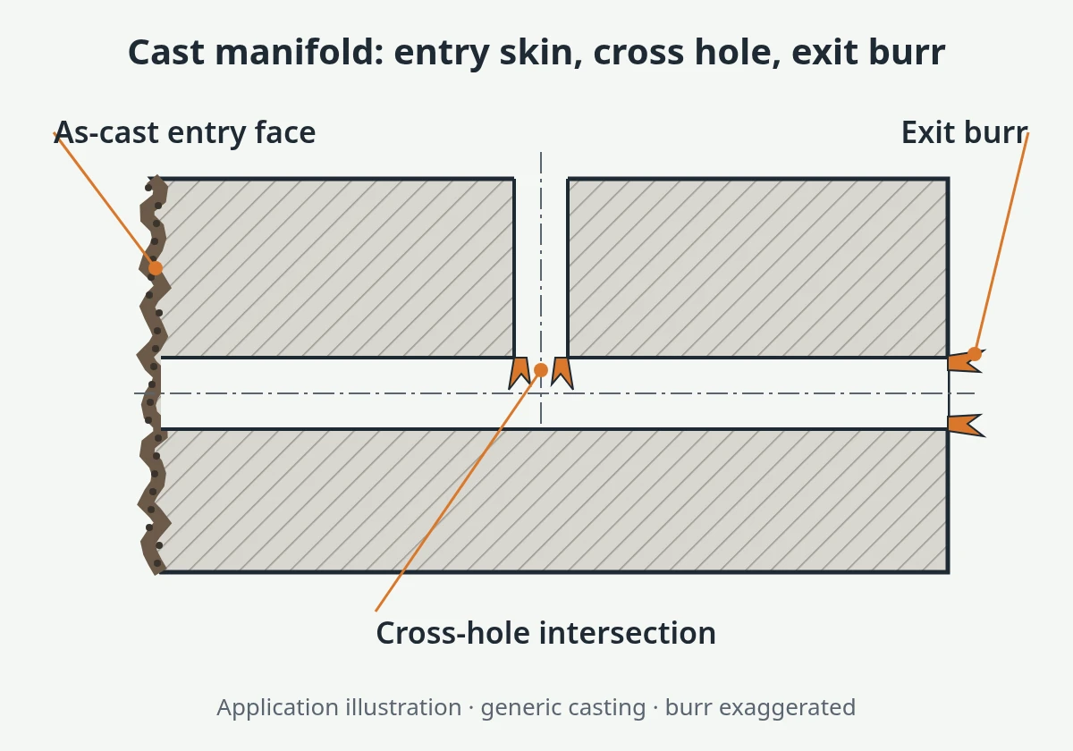
At the intersection. When the drill breaks into a cross hole, part of the cutting edge is suddenly cutting air, then metal again. When the exit edge crumbles in gray iron, first check the feed at breakthrough and whether the outer corners are still sharp and protected. In ductile iron the same breakthrough usually leaves a burr instead. The load cycle is the same in both. How to manage the entry into and through the interruption is in carbide drilling interrupted cuts and cross holes.
At the exit. Ductile iron is the one that burrs. The burr stays attached at the exit face and around the intersection, which is where it is hardest to reach. Easing the feed as the drill breaks through, keeping the outer corners sharp and protected, and planning a deburr or back-chamfer operation where the drawing needs a clean edge all help more than a change of grade. Which hole is drilled first decides where the burr lands and whether a deburring tool can reach it, so fix that on the process route, not at the machine. Exit support and breakthrough feed in more detail: carbide drill exit breakout and burr control.
Thin walls and inclined exits. A thin web between two galleries flexes under thrust and can break out before the drill has finished. An inclined exit loads one lip first. Both are covered, with the entry side, in drilling inclined, cross-hole and thin-wall exits with solid carbide.
Flute Count and Point for Short-Chip Iron
Cast iron is the usual reason to consider a three-flute carbide drill. In gray iron the chip is short enough for the narrower flutes, and the third margin gives better guidance for roundness and position, provided the machine, holder and fixture are rigid. Ductile iron is a different case. A three-flute drill fits only when its chips break short in your process. When they come off longer, the chip room of a two-flute drill is the safer start. The trade-offs are set out on two vs three flutes and point angle selection, and they apply here unchanged.
At the point, the outer corner is where abrasion and cast skin do the most damage. A flatter point angle makes that corner more acute, so it is sharper but weaker. That is why drills for cast iron often have a second, smaller angle ground at the corner (a double-angle point) or a corner chamfer or radius. These spread the load at the corner and soften the exit. Treat them as options to discuss against the drawing, not as defaults.
What to Send for a Cast Iron Drill Recommendation
A request for "a carbide drill for cast iron" can be answered many ways. These fields narrow it down to your part:
- Material grade as written on the drawing or certificate (e.g. EN-GJL-250 or EN-GJS-500-7), not just "cast iron"
- Hardness measured on the parts, if available, and whether it varies between castings or suppliers
- Surface at entry: as-cast, pre-machined, spot-faced, sloped, or on a boss with draft
- Coolant methods the machine actually has: dry, air, MQL (type), flood, through-tool, and the filtration
- Dust extraction: at the spindle, enclosure only, or none
- Hole data: diameter, depth, blind or through, and whether the depth is to full diameter or to the drill point
- Cross holes and intersections, with a sketch of which hole is drilled first and which exits are in the acceptance
- Tolerance and finish, and the next operation (ream, tap, bore, none)
- Machine, spindle interface, holder, stickout, and measured runout if you have it
- Current drill and result: designation, how long it runs, how it fails (corner wear, chipping, packing, burr, size), and photos of the corners and the hole
If you run the same part in gray and ductile iron, say so and send both grades. A drill that works for both can be discussed, but it is a compromise and should be tested in each material. Coating for gray or ductile iron is chosen together with the point and flutes once these fields are known.
Frequently Asked Questions
Can you drill cast iron dry with a carbide drill?
Often, in gray iron, when the hole is shallow and through, the chips and dust can leave the hole, and the machine extracts the dust. Deep holes, blind holes, holes that break into cross passages, tolerance holes and most ductile iron usually need MQL or through-tool coolant, because chips and heat have nowhere else to go. Decide hole by hole, not for "cast iron" as a whole.
Is ductile iron harder to drill than gray iron?
Usually, yes. Ductile iron's nodular graphite leaves a tougher matrix, so chips are longer, cutting force and edge heat are higher, and exit burrs are larger. Gray iron's flake graphite breaks the chip and lubricates the cut, so its main issues are dust and abrasive wear. Wear depends mainly on the matrix, pearlitic or ferritic, and on hardness, not only on whether the iron is gray or ductile.
What carbide drill is best for cast iron?
No single drill is best. The choice follows the grade and its hardness, the hole depth and type, the coolant method and the entry face. A three-flute drill suits gray iron on a rigid setup, and ductile iron often needs a two-flute drill unless its chips break short. Corner protection at the point matters in both. Use choosing a carbide drill series by material to find the starting family, and the carbide drill bits overview to see the series.
How do I stop exit burrs when drilling ductile iron cross holes?
Ease the feed as the drill breaks through, keep the outer corners sharp and protected, and support thin exits where you can. Decide which hole is drilled first so the burr lands where a deburring or back-chamfer tool can reach it. Where the drawing needs a burr-free intersection, plan a deburr operation instead of expecting the drill alone to deliver it.
Next step
Send the casting drawing with the grade and the coolant setup you actually have. We will read the holes with you and propose a drill and a coolant route for your approval, then agree the first-article checks with you before any sample is made.