
Aerospace Engine Bores — Concentricity in Metal That Moves When You Cut It
Five bore terms that decide the tool
These five words carry most of the disagreement in an engine-bore quote. Read them before the diameter, because each one points to a different part of the process.
| Term | What it controls | Why it changes the tool |
|---|---|---|
| Casing bore | A bore opened in a cast or forged housing, often with an interrupted entry | Interrupted entry and thin walls favour a rigid drill and a boring head over a reamer |
| Seal bore | A bore that carries a seal or bushing, usually deep and small relative to its length | Length-to-diameter ratio decides whether the tool can be guided at the far end |
| Roundness vs cylindricity | Roundness is one cross-section; cylindricity is the whole length | A bore can be round at every station and still fail cylindricity through taper |
| Position (concentricity) | Where the bore axis sits relative to a datum, not how big it is | Position is generated from the machine axis, so a reamer that follows the pre-hole cannot correct it |
| Spring-back | The elastic recovery of a thin wall after the clamp opens | Spring-back is why a bore can measure round in the fixture and oval on the bench |
Four ways a casing bore goes out without the diameter changing
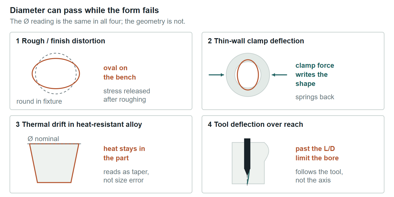
- Distortion between rough and finish. Roughing releases residual stress in a casting or a ring. If the finishing pass is planned from the pre-rough state, the finished bore is round in the fixture and oval on the bench.
- Thin-wall deflection under clamp. Seal lands and ring bores deflect against the clamping force. The cut is a copy of the clamped shape, so the part springs back to a different geometry the moment the fixture opens.
- Thermal growth in heat-resistant alloys. Inconel and similar grades hold heat at the edge and in the part. A bore cut without a thermal plan drifts dimensionally along the feature, which reads as taper rather than as a size error.
- Tool deflection over reach. Seal bores are often deep and small relative to the required length. Past a certain length-to-diameter ratio the bore follows the tool, not the axis, and the error is a bell-mouth or a lobed section.
The alloy cutting physics that produces these heat and chip conditions is covered on Tough-Alloy Holemaking. This page assumes that physics and addresses what the engine part adds.
Why diameter holds while form fails
Diameter is set by the cutting edge. Form is set by the machine axis, the fixture and the heat in the part. That is the whole reason a bore can pass a Ø check and still fail a roundness or position callout on the same drawing.
Diameter follows the tool
A reamer cuts to its own diameter, so size follows the tool. But a reamer also follows the pre-hole, so if the pre-hole was drilled off-axis the reamer reproduces that position error at the correct size. Boring is generated from the machine axis instead, so it can correct position — but only when the setup holds the part where the machine expects it.
Form follows the setup
In a thin-wall casing the fixture is part of the geometry. Clamp the wall and it moves; cut the moved shape and you have cut a shape the part will not hold once the clamp opens. The measurement that counts is taken with the part free and at thermal equilibrium, not in the fixture.
Why a thin-wall bore is round in the fixture and oval on the bench
Clamping a thin wall is a load, not a location. The clamp force pushes the wall in, the bore cross-section goes from round to a tall oval, and the finishing cut copies that clamped oval because the tool is cutting the material where the clamp has put it.
Open the fixture and the elastic energy comes back. The wall springs out, the bore goes wide, and the part now measures oval with a diameter that is still inside tolerance. No finishing tool can recover this, because the tool never saw the free shape — it cut the clamped one.
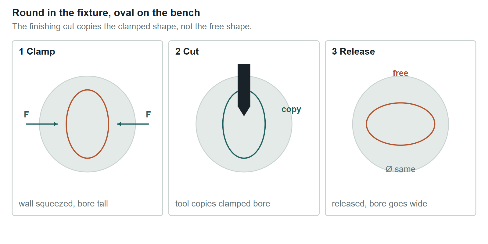
What changes the outcome is a support that holds the wall without loading it into a new shape: a closer-fitting support, lower clamp force spread over more area, or a sequence that finishes the bore after the clamp load is removed. That is a setup decision, and it belongs in the RFQ together with the bore schedule.
What drives tooling on engine and actuation bores
| Feature | What usually decides the tool | HENTRY entry |
|---|---|---|
| Deep seal or bushing bore | Length-to-diameter ratio and whether the tool can be guided at the far end | Fine Boring Tools · Carbide Reamer |
| Bore opened from solid in a casing | Interrupted entry, coolant reach and chip room at the bottom | Through-Coolant Carbide Drills · Indexable Drills |
| Seal land and groove faces | Whether the form can be cut in one pass; a second pass leaves a witness line on a sealing face | Grooving Tools · Custom End Mills |
| Thin-wall ring and liner sections | Cutting force, because force is what deflects the wall | Roughing End Mills · High Feed End Mills |
| Hard-turned seal diameters | Hardness that rules out carbide geometry entirely | CBN / PCBN Inserts |
Which alloy pushes you where
| Material | Route | Why |
|---|---|---|
| Inconel 718 and similar nickel grades | Carbide with a geometry that keeps the cut under the work-hardened layer | Every pass that rubs instead of cuts hardens the next one; the bore tightens as you go |
| Ti-6Al-4V casings and fittings | Carbide, generous coolant, no dwelling at the bore bottom | Heat stays at the edge; a pause at the bottom welds chip material to the flank |
| 17-4PH and 15-5PH stainless | Carbide with edge prep, sharp but not fragile | Work hardening and a tendency to smear on a dull edge |
| Aluminum actuation housings | Carbide drill, PCD ream where finish or wear life is the limit | Clean shear; PCD earns its place on life rather than on capability |
| Hardened or sprayed seal surfaces | CBN turning or grinding route, not a reamer | Above a certain hardness a multi-flute reamer cannot cut cleanly at all |
Boundaries, so you do not read the wrong page
- Fastener holes in airframe structure — interference fit, stacks and exit burr → Aerospace Fastener Hole Machining.
- The alloy heat and chip problem on its own → Tough-Alloy Holemaking.
- Aluminum housings on line takt with no engine-specific requirement → Automotive & EV Powertrain.
- Records and requalification after a tool change → Aerospace Tool Traceability.
Measure the bore the way the print is judged
A bore that reads good in the fixture and bad on the bench was measured in the wrong state. Judge it free, at thermal equilibrium, and at the temperature the drawing assumes. If the shop measures in the fixture because that is where the CMM can reach, the number is not the number the print is asking for.
For a thin wall, a free-state check before the finish pass shows whether the clamp is writing the shape: measure, release, measure again, and compare. A difference larger than the roundness callout means the setup, not the tool, is setting the result.
Which route fits which bore problem
Read the measured error first, then pick the route. The table is conditional: every row has a condition that sends you elsewhere.
| Situation | Likely route | Rule it out when | What to verify next |
|---|---|---|---|
| Bore round in fixture, oval on bench | Fix clamping and support; finish after clamp release | The wall is thick enough that clamp force cannot move it | Free-state roundness at thermal equilibrium |
| Bore on size but off position | Boring from the machine axis, not reaming from the pre-hole | The pre-hole already holds position inside the callout | Pre-hole position and the setup datum |
| Taper along a deep seal bore | Thermal plan: coolant, dwell control, a mid-feature check | The taper is geometric, from a misaligned axis | Bore measured at both ends at one temperature |
| Bell-mouth or lobed section | Lower the length-to-diameter ratio or add far-end guidance | The L/D is already low and the error comes from the pre-hole | Tool runout and stickout |
| Oval in a hardened or sprayed surface | CBN turning or grinding, not a reamer | Hardness is low enough for a multi-flute reamer to cut | Hardness and whether the surface is sprayed |
| Distortion between rough and finish | Stress-relieve before finishing and leave finishing stock | The part is already stress-relieved and stable | Bore measured before and after a stabilising pass |
None of these rows is decided by the tool alone. The measured error, the clamping state and the material condition together pick the route, and the tool follows from that.
What makes an engine-bore quote reviewable
- Bore Ø, tolerance, roundness, cylindricity and the length-to-diameter ratio
- Operation sequence as it runs today, including where rough and finish are separated
- Material, condition and whether the part is stress-relieved before finishing
- Clamping and support method, and the wall thickness around the bore
- Machine, holder, stickout, measured runout and coolant pressure
- The measured error you see on the released part — taper, bell-mouth, ovality, position
Quick answers before you RFQ
Is a reamer or a boring tool the right answer for a seal bore?
It depends on how the error is distributed. A reamer follows the pre-hole, so it corrects size and surface but not position. Boring corrects position because it is generated from the machine axis, but it is slower and needs a rigid setup. Where the print controls position and roundness together, boring is usually the honest route; where it controls size and finish on a good pre-hole, reaming is faster.
Can tooling fix a bore that is oval after unclamping?
Not on its own. If the part measures round in the fixture and oval on the bench, the material is springing back and the clamp is writing the geometry. A finishing tool cannot correct a shape the part only holds under load. Send the clamping method with the print and that gets reviewed before the tool is quoted.
Does PCD have a place in engine work?
On aluminum actuation housings, yes, where finish or wear life justifies it. On nickel and titanium it does not — the failure is thermal and adhesive rather than abrasive, and PCD does not solve either.
Where does the fastener-hole work belong?
On Aerospace Fastener Hole Machining. The tool families overlap, but a fastener hole is a fit problem in a stack and a casing bore is a position and distortion problem. They are quoted from different information.
Send the bore schedule with the clamping method
Primary tooling entries for engine and actuation bores: fine boring tools, carbide reamers, through-coolant and indexable drills, and grooving geometry for seal faces. The clamping plan is reviewed with the tool, not after it.