
Yesterday the bore passed. Today the gauge on the line reads over the upper limit. Every part since the last good check is in quarantine, and someone has to decide within the hour whether to change the reamer, move an offset, or stop the line. The tool might be brand new, it might have just come back from regrind, or it might have been running all shift. On the floor it comes down to one question: is it the reamer or the setup?
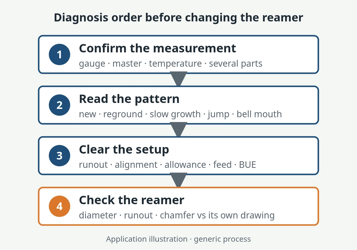
Changing the tool first is the expensive guess. If the cause is runout in the holder, a warm part, or a pre-hole that has moved, a new reamer cuts the same oversize bore, and now two tools are under suspicion. Work in order instead: prove the oversize is real, read when and where it appears, clear the setup, and only then measure the reamer against its own drawing. The last section lists the data to send with a returned tool or a new RFQ. If your bores are going the other way, see the undersize hole diagnosis for ADC12.
When a reamer cuts oversize, check in this order: first the measurement (gauge, temperature, depth, several parts), then the pattern (new tool, just reground, slow growth, sudden jump, or entry bell mouth), then assembled runout, alignment, allowance, feed, and built-up edge. Blame the reamer's own diameter, runout, or chamfer only after those are clear. The pattern usually tells you more than the tool certificate does.
First Confirm the Hole Is Really Oversize
Most wrong tool changes start with one reading on one part. Before you touch the process, check four things.
Compare with the limits, not the nominal size. For an H-class hole such as H7, the lower deviation is zero, so every good hole measures at or above nominal. A bore that is bigger than nominal is not oversize. It is oversize when it is above the upper limit. Confirm which limit the gauge is set to and which master was used to set it.
Check the gauge and master. Set the gauge on the correct master in the same session. If two methods disagree, for example a two-point bore gauge and a three-point gauge, or an air gauge and a CMM, the hole may be lobed rather than oversize. A lobed hole is a roundness problem with a different cause chain. Settle the disagreement before you judge the size.
Watch part temperature. A part measured straight off the machine, with a gauge set on a room-temperature master, can read differently from the same part once it has settled. How much, and in which direction, depends on the part material, the gauge, and how warm the part is. Measure at the reference temperature the drawing assumes (20 °C under ISO 1 unless stated), or at least measure every part at the same stage after machining.
Measure more than one spot and one part. Measure the entry, the middle, and the exit, on several consecutive parts, not just the one that failed. Note the part sequence number or the tool's hole count for each reading. The next section works from that record.
Read the Pattern: When and Where the Oversize Appears
The fault tree on how PCD reamers control hole accuracy and surface finish gives the first checks for each defect mode. Once you know the problem is oversize, timing and location narrow it down further. A bore that was oversize from the first part has a different cause list from one that grew over a shift, and an entry-only oversize is different from a bore that is large all the way down.
| Pattern | First suspects | Check before blaming the tool |
|---|---|---|
| Oversize from the first part with a new tool | Something mechanical in the new assembly or in the tool: assembled runout, a holder or collet swapped along with the tool, misalignment, or a tool diameter sitting in the wrong part of its band | Assembled runout at the cutting edge, in the production holder; tool diameter over the margins against the tool drawing |
| Oversize right after a regrind | The service itself: diameter, runout, lead or chamfer symmetry, or a pre-service offset carried over | The requalification record from the regrind; a fresh preset; runout in the production holder |
| Size grows slowly over a run | Material picked up on the margins or edge (built-up edge, especially in aluminum); coolant concentration or delivery drifting; part temperature rising | The margins under magnification; coolant condition and aim; a part measured after it has cooled to reference temperature |
| Sudden jump between two parts | Something happened: a chip recut or packed flute, a chipped edge, the tool pulled or knocked in the holder, a collision, or a change in the previous operation | The edge and margins; holder seating; what changed at that part number (drill swap, fixture, offset, operator) |
| Oversize at the entry only (bell mouth) | The reamer's cutting portion out of line with the hole when it starts cutting; long stickout; no guidance | Tool axis vs pre-hole axis; stickout; holder type; whether the entry face is square |
| Oversize along the whole bore, with taper | Pre-hole position or taper; deflection; allowance heavier at one end | Pre-hole size and position at entry and at depth; allowance at both ends |
Wear on a reamer usually shows up as a smaller bore, not a larger one, because it removes material from the cutting edge and margins. So when a bore grows slowly over a run, look for pickup before you blame wear. Treat that as a first suspect, not a verdict: galled margins can hide wear underneath.
Bell Mouth, Uniform Oversize, or Taper
These three shapes can look the same if you only take one reading at the entry. Measure at three depths and they separate:
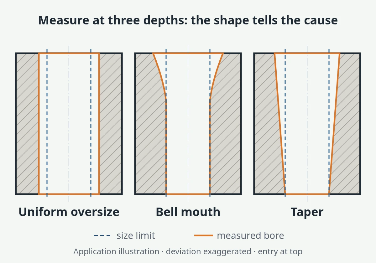
- Bell mouth: oversize at the entry, coming back toward size further in. The cutting portion was not lined up with the hole when it started; once the reamer body was guided, the size recovered. Look at alignment and entry conditions, not at tool diameter.
- Uniform oversize: the same oversize at every depth. The reamer, or the assembly, is cutting a larger circle. Look at tool diameter, runout at the cutting edge, and material stuck to the margins.
- Taper: size changes steadily from entry to exit. Look at the pre-hole, deflection from long stickout, and whether chips pack at the bottom of a blind hole.
Setup Causes to Clear Before Changing the Reamer
Each of these checks has its own page on this site. Here we only cover what each one looks like when the complaint is oversize.
Assembled runout at the cutting edge. Measure the spindle, holder, and reamer together, as close to the cutting edges as you safely can, at the stickout you cut with. A holder catalogue figure or a bench reading is not that number. With runout, one edge cuts more than the others, and the bore comes out larger than the tool. The procedure is in the PCD reamer presetting and assembled runout checklist.
Alignment with the pre-hole. A reamer follows the hole it is given. It does not correct the position of a drilled hole. If the spindle axis and the pre-hole axis are offset or tilted, a rigid holder makes the reamer cut its way across, and the entry comes out large. Check where the pre-hole actually is, and how round and straight it is (pre-hole quality beyond allowance size), before you assume it sits on the reamer's axis. If the drilled hole is already oversize, the problem is upstream: diagnose the drill first (oversized holes with a new carbide drill).
Floating or rigid holder. A floating holder lets the reamer find the pre-hole axis when the machine and the hole are out of line. It does nothing about runout inside the tool or the holder. On a rigid, well-aligned machine it may add movement; verify it on your setup. Use it for misalignment you cannot remove, not as a general fix. Choosing the holder in the first place is a separate step, covered in floating vs rigid holder selection.
Allowance and feed. With too little stock, or too light a feed, the reamer rubs instead of cutting. Rubbing heats the wall, and the size can open up or wander from part to part. Too much stock for the chip space can push the reamer off line as well. Qualitative allowance guidance by pre-hole method is in PCD reamer allowance and pre-hole size. There are no universal speed or feed numbers for this, because they depend on the tool, the material, and the machine.
Built-up edge and coolant. In aluminum, material that sticks to the edge or margins makes the effective cutting diameter larger, and it changes from part to part. Check that the coolant actually reaches the edges and that its concentration has not drifted, since coolant condition also affects cut size. The full sequence is in controlling built-up edge when PCD reaming high-silicon aluminum.
Chatter marks with the oversize. If the bore also shows chatter marks or lobing, deal with the vibration first: PCD reamer chatter diagnosis.
When the Oversize Is the Reamer Itself
You get to this step when the measurement is confirmed, the pattern points at the tool, and runout, alignment, allowance, and built-up edge have been cleared. You also get here when a second, known-good reamer in the same holder cuts to size and this one does not. On a production line, that swap test is the cleanest evidence you can get.
Diameter over the margins, against the tool's own band. Measure the tool, not only the hole, and compare it with the tolerance on the tool drawing or inspection report, not with the hole limits. A reamer with an odd number of flutes cannot be measured across two opposite margins with a standard micrometer, so use a method that suits the flute count. The fields a tool inspection report should carry are listed in what inspection pack to require for a custom PCD reamer.
The wrong band on the order. The hole tolerance and the reamer tolerance are different things. A reamer ordered simply "to H7" may have been made anywhere inside the hole's limits, with no room left for how your process cuts. Depending on material, runout, and edge condition, the bore can come out slightly larger or smaller than the tool. If the tool measures near the top of the hole band, the bore will tend to go over. How to set the reamer's own band for an H7 hole is covered in reamer tolerance for H7 holes.
Unequal lead or chamfer, or runout of the cutting end. If one lead is higher or longer than the others, that edge does more of the cutting. A bent or non-concentric shank, often the result of a collision or a drop, has the same effect.
Margin damage, pickup, or a chipped edge. Look at the margins and edges under magnification. Galled material on a margin raises the cut size, and a chipped edge tears the wall instead of cutting it cleanly.
PCD Reamer Oversize vs Carbide: What Differs
The order is the same for both. Two things change the weighting:
- Adhesion. A sharp PCD edge and its low friction against aluminum reduce the tendency to build up an edge, but they do not remove it. High-silicon and die-cast aluminum can still stick when coolant is poor or the reamer rubs. "PCD doesn't build up" is not a reason to skip the margin check.
- Regrind and guide pads. A PCD regrind is a service event done by the toolmaker. Diameter, lead, length, and runout can all come back changed, and guided designs follow their pads, so a damaged pad changes the bore. With either material, oversize right after service points first at the service record.
The wider choice between the two materials is covered in PCD reamer vs carbide reamer.
What to Send With a Returned Reamer or an RFQ
"It cuts oversize" plus a tool in a box cannot be diagnosed. The same data that settles the question on the line settles it at the toolmaker:
- Measured bore sizes on several consecutive parts, at entry, middle, and exit, with the part sequence or hole count
- Gauge type, the master used, and when each part was measured after machining
- The pattern: from the first part, after regrind, growing from a given hole count, a jump at a given part, or entry only
- The tool's measured diameter and its assembled runout in the production holder, with the measuring position
- Pre-hole size and position at entry and at depth, and how the pre-hole is made
- Holder type (rigid, floating, hydraulic, shrink-fit), stickout, and machine
- Workpiece material and condition; coolant type, concentration, and delivery (through-tool or external)
- The speed and feed you are running (your values)
- What you have already changed and what happened, for example "second tool in the same holder, same result"
- Photos of the margins, the cutting edges, and the bore wall
If the reamer goes back for review or regrind, send its tool ID and service history so the inspection can be compared with its last release.
Frequently Asked Questions
Why does a new reamer cut oversize?
When a new reamer cuts oversize from the first part, the cause is usually mechanical: runout at the cutting edge once the tool is mounted, a holder or collet swapped along with the tool, misalignment with the pre-hole, or a tool diameter in the wrong part of its band. Measure assembled runout in the production holder and the tool diameter over the margins before you change anything else. A second tool in the same holder shows which side is at fault.
What causes a bell-mouthed reamed hole?
The cutting portion of the reamer entering at an angle to the hole axis, or offset from it. The size comes back deeper in, once the reamer body is guided. Check spindle-to-pre-hole alignment, stickout, the entry face, and the holder type. Tool diameter is rarely the cause when only the entry is large.
Can a floating holder fix an oversize reamed hole?
Only when the cause is misalignment between the machine axis and the pre-hole that you cannot remove. It does not correct runout inside the reamer or the holder, a tool made too large, built-up edge, or rubbing from too little stock. On a rigid, well-aligned machine, fix the alignment or the runout directly.
Why does my PCD reamer cut oversize after regrinding?
A regrind changes the lead and can change diameter and length, and the tool then goes back into a holder that has to be preset again. Check the requalification record (diameter, runout, lead symmetry, pads), preset again instead of reusing the old offset, and measure runout in the production holder. What to check after service is in the PCD reamer regrind and requalification guide.
Next step
If your bores are going oversize, send us the measured data and the pattern before you order a replacement tool. We will go through it with you and give you our read on whether the evidence points at the setup or at the reamer. When a new or reground reamer does go in, run it on sample parts and freeze the size there before you release volume (sample validation).