
A counterbore is a cylindrical recess with a flat annular seat. A countersink is a conical recess. A spotface is a shallow machined flat around a hole. Choose among them from the fastener head and assembly function first, then define the diameter, depth or included angle, remaining wall, datum relationship and inspection method.
This guide is for process engineers, machinists, quality teams and engineering buyers deciding how a drawing-defined hole entrance should be produced and verified. Use it to identify the required feature first. If the conical feature is already defined and the remaining task is cutter selection, continue to the XRZ guide on countersink versus chamfer mill.
The three features can look similar from the top view, but they do not perform the same job. A counterbore can recess a cylindrical fastener head or provide a controlled shoulder. A countersink supports a tapered fastener head or another drawing-defined conical interface. A spotface creates a local bearing surface without intentionally forming a deep head recess. Confusing them can change clamp load transfer, fastener projection, remaining wall, tool access and inspection.
Quick Answer: The Direct Difference
| Feature | Section geometry | Primary assembly function | Critical drawing inputs | Typical machining routes |
|---|---|---|---|---|
| Counterbore | Cylindrical recess with a flat annular bottom around a smaller hole | Recess a cylindrical head or create a controlled flat shoulder for a head, washer or component | Through-hole diameter, counterbore diameter, depth, bottom/corner condition and specified relationship to the hole axis | Counterbore tool, piloted counterbore, plunge-capable end mill, circular interpolation, or custom combination tool |
| Countersink | Conical recess around the hole entrance | Seat a tapered fastener head, place it flush/below the surface, or create another specified conical interface | Hole diameter, major diameter or depth, included angle, edge condition and concentricity | Countersink tool, chamfer tool or chamfer mill selected for the required angle and access |
| Spotface | Shallow flat cylindrical cut around the hole | Create a local seating/bearing surface on a rough, curved, forged, cast or inclined face | Spotface diameter, clean-up/depth rule, flatness/orientation, surface requirement and relation to the hole | Spotface tool, piloted spotfacer, counterbore-style tool, end mill or custom tool |
Do not select the feature by tool name. A counterbore tool can sometimes generate a spotface, and an end mill can sometimes generate a counterbore, but the finished geometry and assembly requirement remain the controlling definitions.
XRZ Four-Branch Feature Gate
Start with the contact function at assembly, not with the cutter already available in the toolroom.
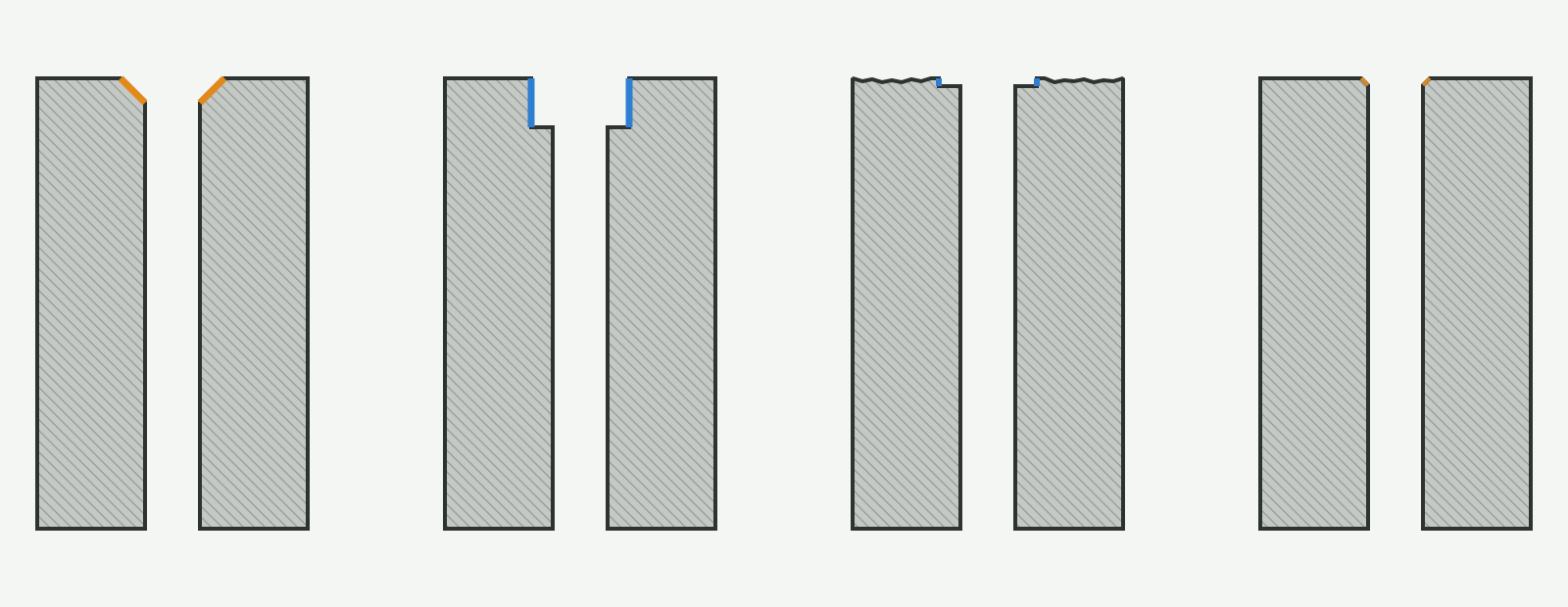
The first question is what must contact the machined surface:
- A tapered fastener head leads to a countersink, provided its included angle and seating requirement are defined.
- A cylindrical head that must be recessed leads to a counterbore, with depth and remaining floor checked together.
- A head, nut or washer that only needs a local bearing clean-up leads to a spotface, with a controlled clean-up or depth limit.
- A sharp edge that only needs removal leads to a chamfer or edge break, not automatically to a fastener countersink.
If none of these describes the assembly, stop and clarify the drawing. A tool should not be selected to manufacture an undefined interface.
Section Geometry: Cylindrical Recess, Cone and Shallow Flat
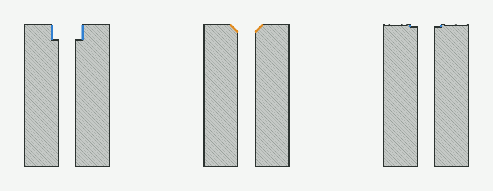
Counterbore geometry
A counterbore has a larger cylindrical diameter above a smaller hole. Its defining surface is the flat annular seat between the two diameters. The designer may also control the wall, bottom corner, transition, depth and the specified relationship between the recess and hole axis.
The word "flat" does not mean every cutter automatically produces a perfectly sharp internal corner. Cutter corner radius, end geometry, runout, deflection and burr formation affect the actual profile. If a fastener head, washer or mating component approaches the internal corner, define the permitted corner radius or relief instead of relying on an idealized section view.
Depth must be tied to the required fastener position and remaining material. A deep counterbore can reduce wall or floor thickness, intersect another feature, weaken a thin flange or restrict chip evacuation. A shallow counterbore may leave a head proud when the design expects it to sit flush or below the surrounding surface.
Countersink geometry
A countersink is defined by a cone, normally specified by its included angle together with a major diameter, depth or resulting fastener position. The angle must match the drawing and the intended mating surface. Do not infer it from a familiar fastener family or substitute a chamfer value without checking the specification.
The same major diameter can produce different axial depths at different included angles. Conversely, a small depth change can move the major diameter and fastener position. For that reason, choose one unambiguous control method and state how the feature will be measured.
A countersink is not automatically an edge-break chamfer. A fastener seat transfers load through a defined conical interface; an edge break removes a sharp edge and usually has a different functional priority. Cutter selection is a separate decision made after this feature has been defined.
Spotface geometry
A spotface resembles a very shallow counterbore in section, but its function is local surface preparation. It removes only enough material to establish the specified seating area around the hole. This is useful when the original face is cast, forged, curved, inclined or otherwise unsuitable for direct contact by a bolt head, nut or washer.
The drawing should state whether depth is fixed, limited by a maximum, or governed by complete clean-up of the required diameter. "Clean up" must not become permission to remove unlimited material. If the starting surface varies, the designer and manufacturing team need an agreed maximum depth or minimum remaining thickness.
Selection Table: Start with the Fastener and Assembly Function
| Assembly need | Preferred feature | Why | Verify before release |
|---|---|---|---|
| Cylindrical socket-head or other straight-sided head must sit below or within the surface | Counterbore | Provides radial clearance and a flat seat at a controlled depth | Head diameter/height, tool clearance, remaining floor, corner radius and installation access |
| Flat or tapered head must sit flush or below the surface | Countersink | Matches a defined conical underside | Fastener standard, included angle, major diameter/depth, head projection and contact pattern |
| Bolt head, nut or washer needs a local bearing surface on a rough or non-normal face | Spotface | Creates a shallow flat contact area without a deep head recess | Required bearing diameter, clean-up, orientation, surface, wall thickness and wrench access |
| Washer or component needs a deep cylindrical register rather than only a local clean-up | Counterbore or another defined recess | Controls both radial location/clearance and axial seating depth | Whether the feature is a fastener counterbore, a precision recess or a separate fitted diameter |
| Only a sharp edge must be removed | Chamfer or edge break, not automatically a countersink | Edge treatment does not necessarily create a functional fastener seat | Chamfer size/angle, burr direction and whether a mating cone exists |
If the fastener has not been selected, do not finalize the recess. Obtain the head style, nominal size, governing fastener standard, actual head envelope where necessary, washer use, assembly tool clearance and required installed position. A nominal thread designation alone does not define the head seat.
Read the Drawing Before Selecting the Tool
ASME Y14.5 provides a framework for dimensioning and tolerancing, but the applicable drawing standard, revision and company practice must be confirmed for the job (ASME Y14.5). Do not interpret a symbol in isolation from the complete hole note, section view, general notes and referenced standards.
Counterbore and spotface callouts
A counterbore callout normally needs the smaller hole size, larger recess diameter and recess depth. It may also need a bottom requirement, corner radius, surface texture, position, runout or another specified relationship between the recess and hole axis, plus the datum from which depth is evaluated.
A spotface callout needs the finished spotface diameter and a clear axial requirement. Depending on design intent, this may be a specified depth, a maximum depth, or sufficient cut to produce complete clean-up. Also define flatness or orientation when the seating plane is functional, plus the surface requirement and the datum from which it is evaluated.
Because the counterbore and spotface symbols can be closely related in common drawing practice, the accompanying dimensions and feature function are decisive. When a note is incomplete, raise a drawing question rather than choosing a depth on the machine.
Countersink callouts
A countersink callout should define the smaller hole and the conical feature using the included angle plus a major diameter, depth or another unambiguous size control. The measurement plan must match the callout. A diameter measured at the top surface, a depth measured along the axis and the installed fastener position are related, but they are not interchangeable inspection results.
Also check whether the drawing controls the feature relative to the hole axis, a datum plane or the surrounding surface. On an inclined or irregular face, a nominal diameter alone may not describe the functional contact area.
Separate the requirement from the process value
The drawing contains product requirements. Cutter diameter, programmed depth, tool length offset and interpolation path are process values used to reach those requirements. Do not copy a finished-feature diameter directly into a tool diameter field without considering interpolation, runout, corner radius and allowance. Likewise, a countersink tool's nominal angle does not prove the finished cone or fastener contact.
Choose the Machining Tool and Path
The feature name does not force one cutter. Use the following XRZ routing matrix to connect the drawing requirement to a practical first tool and its main release risk.
| Feature | Preferred first tool | Alternative path | Main limitation to verify |
|---|---|---|---|
| Counterbore | Dedicated or piloted counterbore | Plunge-capable end mill or end-mill interpolation | Seat bottom, internal corner, pilot compatibility, reach and holder clearance |
| Countersink | Countersink or angle-matched chamfer tool | Chamfer-mill interpolation | Included angle, contact band, chatter, programmed diameter and inspection method |
| Spotface | Dedicated spotface tool | Counterbore-style tool or end mill | Clean-up depth, seat orientation, interrupted entry and remaining wall |
| Multi-level combined hole | Drawing-specific combination tool | Separate tools and operations | Shared speed/feed window, chip path, section wear and independent correction needs |
This matrix chooses the process route, not a universal tool construction. Workpiece material, feature size, entry condition, production quantity and machine access still determine substrate, flute form, coolant route and holder.
Counterbore tool or piloted counterbore
A dedicated counterbore can create the cylindrical wall and flat seat in one axial operation. A pilot may guide the cutter from an existing hole, but pilot fit, hole variation, chip clearance and the risk of marking the hole must be evaluated. A rigid guided route is useful only when the pilot and pre-hole are compatible.
Select the cutter from the required recess diameter, depth, bottom/corner form, material, pre-hole, access and machine capability. Confirm whether the tool is center cutting, requires a pilot hole, or leaves a center feature that conflicts with the design.
Countersink tool or chamfer mill
A countersink tool is selected around the conical feature and access. A chamfer mill may plunge or interpolate depending on its geometry and the required diameter range. The decision involves contact length, chatter risk, spindle path, feature diameter, angle and whether the operation creates a fastener seat or only an edge treatment.
This page does not repeat the full tool comparison. Continue to countersink versus chamfer mill after carbide drilling when the conical feature is already defined.
End mill
An end mill can produce a counterbore or spotface by plunging, circular interpolation or a pocketing path when its center-cutting capability, corner geometry, reach and holder clearance support the operation. Interpolation can cover multiple recess diameters with one tool and permits radial compensation, but it introduces a programmed path and can leave toolpath-related form or witness marks.
Do not assume any end mill can plunge on center. Confirm the flute and center geometry, entry method, axial and radial engagement, chip evacuation and bottom profile. On a small counterbore, the tool may not have enough path radius to interpolate cleanly. On a large shallow spotface, a small cutter may require a longer path and create surface variation if the setup or tool is not controlled.
Spotface tool
A dedicated spotface tool is useful when the required bearing diameter, shallow depth and access favor a direct axial cut. Piloted or back-spotfacing constructions may be needed when the surface lies on the far side of a feature, but restricted access changes tool strength, actuation, chip evacuation and inspection.
XRZ has a dedicated PCD chamfer and spotface route for compatible aluminum applications. PCD spotfacing is for aluminum only. It is not a spotface material for steel, stainless steel, cast iron, or hardened steel. Confirm the workpiece material, interruption and edge contact before selecting it.
Thin Walls, Cast Surfaces and Restricted Access
Thin walls and limited remaining material
For the same seat diameter, a counterbore normally removes more axial material than a spotface. Radial material removal depends on the specified feature diameter. Before machining, check minimum floor thickness, distance to the outer wall, nearby cross holes and the load path under the fastener. Cutting forces can deflect a thin flange, while clamping can distort the same area during inspection or assembly.
Use the drawing model and section views to identify breakthrough risk. If the recess intersects another feature, plan chip exit, burr control and the order of operations. The XRZ guide to inclined, cross-hole and thin-wall drilling provides the related drilling-entry and breakout considerations.
Cast, forged, curved or inclined surfaces
An irregular starting surface creates interrupted contact. One side of the cutter may engage before the other, which can increase deflection, chatter or edge loading. A spotface must cut enough to establish the required bearing area, but variable casting stock can cause part-to-part depth variation.
Decide whether the finished seat must be normal to the hole axis or aligned to another datum. These are not always the same on an inclined face. If the seat orientation carries assembly load, define and inspect it instead of treating the operation as cosmetic clean-up.
Restricted space and back-side features
Toolholder diameter, spindle nose, adjacent walls, fastener-installation access and chip evacuation can constrain the tool before cutting begins. A long-reach end mill may access the feature but lose rigidity. A piloted tool may improve guidance but require room for the pilot and a compatible pre-hole. Back spotfacing may avoid another setup, but the tool mechanism and return path need validation.
Model the complete tool and holder, not only the cutting diameter. Verify collision clearance at approach, cutting depth and retraction.
When a Combination Tool Makes Sense
A combination tool can integrate drilling with counterboring, countersinking, spotfacing, stepping or another hole operation. Integration is justified when the features repeat at sufficient volume and can share a compatible cutting window.
Use a combination route when:
- the hole and entrance feature share a reliable datum strategy;
- all cutting sections can operate within compatible speed, feed and coolant conditions;
- chip flow from one section does not damage or obstruct another;
- tool length, machine power and holder rigidity support the combined engagement;
- section-by-section wear can be monitored and serviced;
- fewer tool changes may save time, but that saving is not approval by itself and does not replace the validation burden;
- sample inspection can verify every integrated feature.
Keep separate tools when one feature needs independent correction, materials or interruptions create incompatible edge requirements, different sections wear at very different rates, or a drawing change would make the combined tool difficult to reuse. The XRZ article on combination tools and cycle-time reduction explains why station reduction is valuable only when the shared process window is real.
XRZ combine-or-separate gate
| Engineering question | Evidence that supports combining | Evidence that supports separate tools |
|---|---|---|
| Can all sections use one spindle-speed and feed strategy? | Each edge works inside an overlapping released window | One section needs materially different conditions or independent compensation |
| Can chips leave without crossing another critical edge or finished seat? | Flute and coolant route clear every section in the cutting sequence | Chips pack between steps, recut on a seat or obstruct a finishing edge |
| Can wear be managed at the section level? | The limiting section is serviceable and its change criterion protects the others | One short-life section discards substantial usable tool or cannot be inspected |
| Does one body preserve a useful datum relationship? | One setup reduces transfers and the result is verified from drawing datums | Separate correction is needed for position, diameter, angle or seat orientation |
| Is the production demand repeatable enough? | Revision, volume and repeat-order controls justify dedicated engineering | Low repeat volume or frequent drawing changes favor standard separate tools |
Do not approve a combination tool from cycle-time arithmetic alone. Release it only when the common cutting window, chip path, wear logic and inspection plan are all defined.
For a custom tool review, XRZ needs the complete feature stack, not merely the words "counterbore" or "spotface." The design input must show the pilot hole, recess, cone or seat, chamfers, tolerances, datum relationships and inspection plan.
Machining and Inspection Data Checklist
Send or confirm the following before selecting the cutter or quoting a custom combination tool:
- Component drawing, 3D model and revision.
- Exact workpiece material, condition, hardness and starting-surface condition.
- Fastener or mating-component standard, head style, size and actual envelope when required.
- Smaller hole diameter, tolerance, depth and whether it is through or blind.
- Feature type: counterbore, countersink, spotface or edge break.
- Counterbore/spotface diameter, depth or clean-up rule, floor/corner condition and remaining-wall limit.
- Countersink included angle, major diameter or depth, and permitted head position.
- Datum, position, runout or another specified relationship between the recess and hole axis, plus applicable flatness, orientation and surface requirements.
- Machine, spindle interface, holder, maximum tool envelope, reach and access direction.
- Pre-hole condition and operation sequence.
- Coolant route, chip-return path and burr-control requirement.
- Inspection method, gauge or instrument, measurement location and acceptance rule.
- Batch size, annual quantity, automation level and tool-change target.
- Current process, observed defect, photos and measured results if the feature already exists.
For conical features, agree whether inspection will use a dedicated gauge, dimensional measurement, optical/profile method, installed-fastener position or another released method. For counterbores and spotfaces, agree how diameter, depth, seat orientation, flatness and surface will be assessed. The inspection plan must evaluate the drawing requirement, not merely confirm that the programmed tool path ran.
XRZ Process Route
Use the XRZ countersink product route for a defined flush fastener seat, the PCD chamfer and spotface route for compatible aluminum applications, and the flat-bottom carbide drill route when the primary task is a blind or interrupted flat-bottom hole rather than a fastener recess.
If a standard cutter cannot produce the complete feature under the available access and process conditions, submit the drawing and checklist for a custom cutting-tool review. XRZ should review the geometry, material, machine, feature sequence, chip path and inspection method before proposing a custom or combination construction.
Frequently Asked Questions
Is a spotface just a shallow counterbore?
They can have similar cylindrical, flat-bottom geometry, but the design intent differs. A counterbore normally creates a recess of controlled depth for a head or component. A spotface removes limited material to establish a local bearing surface. The drawing dimensions and function decide the feature.
Can an end mill make a counterbore?
Yes, when the end mill, machine and toolpath can produce the required diameter, depth, bottom and corner form within the inspection requirements. Confirm center-cutting ability for plunging or use a suitable entry/interpolation path.
Is a countersink the same as a chamfer?
Not necessarily. A countersink commonly forms a functional conical fastener seat. A chamfer may be an edge break, deburring feature or assembly lead. The geometry can overlap, but the functional and inspection requirements may differ.
Should a spotface be perpendicular to the hole axis?
Often the intent is to provide a bearing surface associated with the hole, but the released drawing must define the required orientation and datum. On an inclined or irregular surface, do not assume the hole axis and the intended seating plane are interchangeable.