
Repeated tool changes can make a stable holemaking process slower and harder to control. A drill, reamer, chamfer tool, and spotface cutter may each work correctly, yet the complete route still carries extra tool calls, offsets, inspection points, and opportunities for feature-to-feature variation.
This guide explains where combination tools for CNC holemaking add value, with particular attention to combination drill-reamers, stepped features, aluminum housings, and repeat production. It also shows when separate tools remain the safer process. For the broader material and operation map, start with the PCD tooling applications guide.
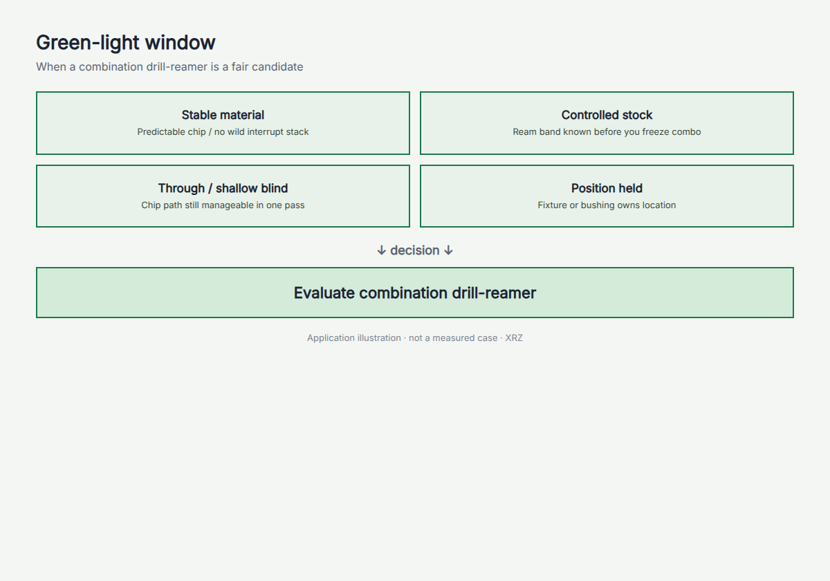
Short answer: For an axial drill-ream combination tool, the related features must be coaxial or otherwise reachable on the designed tool path, and each cutting section must contact the workpiece in the intended sequence. Chip evacuation, tool access, machine stability, section engagement, and inspection must pass the technical review. Stable drawings, repeat volume, fewer tool changes, and reduced offset management then determine whether integration also makes economic sense.
1. Quick Answer: When Should a Combination Tool Be Evaluated?
A combination tool should solve a defined process problem. Reducing the number of tools is useful only after the integrated route passes the required technical gates and can produce accepted parts under a controlled inspection method.
Required technical gates
| Gate | What must be confirmed |
|---|---|
| Feature alignment and access | Axial features are coaxial or arranged so every cutting section can reach the feature and engage in the designed order; a shared datum alone is not enough |
| Chip evacuation | Chips can leave without crossing, packing around, or damaging a finishing edge |
| Cutting conditions | Simultaneously engaged sections have a compatible speed and feed window; sequentially engaged sections can use planned program changes where the machine cycle permits |
| Process stability | Incoming stock, machine, holder, runout, fixture, coolant, and workpiece support are controlled |
| Inspection and service | Each critical feature and tool section can be inspected, diagnosed, and released under defined criteria |
If one of these technical gates fails, keep the operations separate or redesign the process before evaluating the commercial benefit.
Conditions that increase economic value
| Value signal | Why it matters |
|---|---|
| Stable part family and drawing revision | Reduces the risk that a fixed custom geometry becomes obsolete |
| Repeat production volume | Spreads engineering, validation, spare-tool, and service costs across more accepted parts |
| Tool changes or offsets limit the process | Gives integration a measurable cycle-time or process-control target |
| Magazine capacity is constrained | Replacing several tools with one body can release tool positions |
| Related features benefit from one referenced tool path | May reduce transition-related variation when the technical gates are already satisfied |
Use the screen as a technical gate
When all required gates are acceptable and at least one economic value signal is material, Send Your Drawing for an application review. Include the material, current route, engagement sequence, chip path, and rejection mode before a custom tool is frozen.
2. What a Combination Tool Actually Owns
A combination cutting tool places two or more related operations on one tool body. In holemaking, that can include drilling, reaming, chamfering, counterboring, spot facing, or machining multiple diameters.
The tool may reduce machine movements and control relationships between features, but it does not remove the need for a stable machine, holder, fixture, coolant system, or inspection plan. It also does not make every feature equally easy to adjust or service.
Common architectures include:
- Drill-reamer: creates a hole and finishes its diameter and surface in one machining cycle.
- Step, multi-step, or multi-diameter tool: machines two or more related diameters from one referenced body. These multi-step cutting tools are useful only when feature access, engagement order, and chip flow support the combined geometry.
- Drill-ream-chamfer tool: commonly creates and finishes a bore with an entry chamfer. An exit or back-side chamfer requires a dedicated cutting structure, sufficient access space, and a defined machining movement; it is not an automatic capability of a forward-feeding tool.
- Counterbore or spotface combination: controls a bore and a related axial or face feature.
- Form combination tool: produces a drawing-specific profile made from several related diameters, angles, or radii.
This article focuses on application fit. Available configurations, cutting materials, manufacturing options, and quotation scope remain on the custom PCD combination drill-reamer product page.
3. Five Scenarios Where Combination Tools Add Value
1. High-Volume Aluminum Housing Production
Automotive and EV aluminum housings often contain bearing bores, valve bores, locating holes, seal features, steps, and chamfers that repeat across a released part family. When those features share a datum and the process is stable, one custom tool may replace several independent operations.
Typical candidates include EV motor housings, transmission housings, valve bodies, compressor components, pump bodies, cylinder heads, and brake or steering components. The business case becomes stronger when tool changes, offsets, inspection after changes, and accumulated cycle time affect a high number of accepted parts.
Aluminum alone does not make a combination tool suitable. Casting-lot variation, thin-wall distortion, trapped chips, inconsistent pre-machining, and weak clamping can still make a separate route more reliable. Confirm the actual failure mechanism before selecting the tool architecture.
2. Drill, Ream, and Chamfer in One Machining Cycle
A drill-ream-chamfer tool can be useful when the bore and chamfer have a fixed relationship and the machine can support the tool length, coolant path, and required rigidity. Consolidation removes at least one tool change and reduces the number of offsets that must remain synchronized.
The drill section must create a consistent path for the finishing section. The reaming section must receive a controlled allowance rather than random stock. The chamfer section must reach the feature without recutting chips or producing an axial dimension that cannot be inspected.
This route is strongest when the engagement sequence is understood. Sections that cut at the same time need a compatible speed and feed window. When the sections engage in separate phases, the CNC program may change feed or other permitted conditions between phases, provided the tool path, machine, and cutting geometry support that strategy. If neither approach gives every section a safe window, keep the operations separate.
3. Stepped and Coaxial Features With a Reachable Tool Path
Combination tools can control related diameters, steps, counterbores, and chamfers from one referenced tool body when the axial features are coaxial, physically reachable, and positioned so each section contacts the workpiece in the intended sequence. This can reduce variation created by changing tools, loading separate offsets, or transferring the feature between operations.
The advantage is feature relationship, not an automatic improvement in every tolerance. A combination tool cannot correct a hole that has already wandered because of poor guidance, fixture movement, or an unstable entry surface. It also cannot remove workpiece distortion caused by clamping or thin walls.
Use a combination concept when the drawing clearly identifies the critical relationships and the inspection plan can verify each one. If a rejected part cannot be traced to a specific diameter, face, or tool section, service and corrective action become unnecessarily difficult.
4. Production Cells Limited by Tool Changes and Offset Management
Some cells are limited by the movement between operations rather than by the cutting time of one tool. The opportunity may include:
- repeated automatic tool changes;
- limited magazine capacity;
- multiple wear offsets for related features;
- first-piece inspection after each change;
- operator intervention to correct bore drift;
- accumulated positioning time between tools.
Measure those losses before specifying a combination tool. A reduced tool count has commercial value only when it removes real machine time, inspection burden, or variation. The combination-tool cycle-time guide covers that narrower calculation in more detail.
5. Stable Part Families With Repeat Demand
An integral or fixed-geometry combination tool locks several operations into one physical design. That makes revision control, repeat orders, spare tools, and reconditioning strategy more important than they are for a simple standard cutter. Modular, adjustable, or replaceable-head concepts require a separate review of interfaces, adjustment range, rigidity, replacement accuracy, and service procedure.
The strongest candidates normally have a released drawing, repeat demand, defined production equipment, and a stable inspection method. The plant should know which revision is approved and how a replacement tool will be identified and checked.
Low-volume work can still justify a combination tool when a difficult feature relationship or machine limitation creates enough value. However, a frequently changing part or short program may not use enough of the tool's capability to recover the design and validation effort.
Send Your Drawing and current process for a combination-tool review. For a more detailed route-selection sequence, continue with the drill-then-ream versus PCD combination decision tree.
4. When Separate Tools Are the Better Process
The Engagement Sequence Cannot Support the Required Parameters
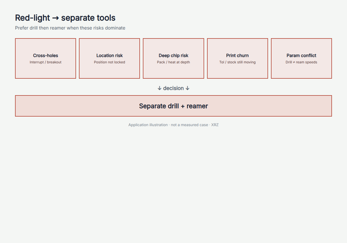
Separate tools allow fully independent speeds, feeds, peck cycles, coolant strategies, and tool-life rules. Keep that freedom when simultaneously engaged sections cannot share a safe speed and feed window, or when sequential engagement and program changes still cannot provide the required conditions for each section.
A combination tool should not be selected by averaging two incompatible parameter windows. The resulting program may be slower than the original route and less stable at both operations.
Chip Evacuation Is Not Yet Controlled
Deep blind holes, cross-holes, interrupted walls, and multiple steps can trap or redirect chips. Drill chips may pass over a finishing edge, become recut, mark the bore, or increase local load.
Internal coolant can help, but coolant pressure alone does not prove that the path is clear. Review flute volume, hole depth, chip shape, exit direction, and the order in which each section engages. The deep blind-hole combination-tool risk guide provides a focused review of this boundary.
One Tool Section Will Wear Much Faster
The economic life of a combination tool can be limited by its weakest or fastest-wearing section. If the drill point reaches end of life long before the reaming edges, the plant may retire or recondition the complete tool while much of its value remains unused.
Before integration, define how each section will be inspected, which section establishes end of life, whether local repair is possible, and how a spare tool will be managed.
Position, Runout, or Fixturing Is Still Unstable
A combination body can reduce transitions, but it cannot replace basic process control. If the current bore is rejected because the fixture moves, the spindle-holder assembly runs out, the entry face is inconsistent, or the workpiece distorts, correct that input first.
Finishing geometry should control size, form, and surface on an appropriate incoming condition. It should not be used as a substitute for locating the feature.
The Drawing Changes Frequently
When one diameter, step, chamfer, or axial dimension changes, an integral or fixed-geometry custom body may require modification or replacement. Separate tools are easier to revise independently and can reduce obsolescence during early product development. Modular, adjustable, or replaceable-head structures should be evaluated against their actual adjustment and replacement scope rather than treated as an integral tool.
The PCD combination-tool wrong-choice guide provides additional stop criteria for projects where a PCD combination concept is already being considered.
5. PCD or Carbide Combination Tool?
Cutting material follows the workpiece, operation, wear mechanism, and economics. It should not be selected from the word "combination" alone.
PCD deserves evaluation for suitable non-ferrous and abrasive materials, particularly stable aluminum production where edge wear creates repeated corrections, tool changes, or bore-quality drift. High-silicon aluminum can strengthen the wear-related case, but silicon content does not remove the need to control allowance, runout, chips, coolant, and inspection.
Carbide generally provides a broader material range and greater flexibility for lower-volume or changing work. It may be more practical for many steels, stainless steels, mixed programs, or applications where the custom tool will not remain in production long enough to use the wear capacity of PCD.
The right comparison is the complete process under the same acceptance criteria. Do not assume that a higher-priced PCD tool or a lower-priced carbide tool will automatically produce the lower cost per accepted part.
6. Related XRZ Validation Evidence
XRZ has published a customer-validated ADC12 EV motor-housing application in which a custom PCD combination reamer replaced a multi-tool route. For the measured tool-life, cycle-time, surface-finish, and coolant results—and the specific conditions that limit how those results may be interpreted—review the full ADC12 validation example.
A new application still requires its own drawing review and sample validation process. The referenced project is evidence of one controlled route, not a performance guarantee for another material, feature, machine, or production line.
7. Compare Cost per Accepted Part, Not Tool Count
A combination tool may cost more than one individual drill or reamer while still reducing the cost of an accepted component. It may also look efficient on a cycle-time estimate and lose economically if one damaged section retires the complete tool.
Compare both routes using the same production period and acceptance rules. Include:
- tool acquisition and any dedicated holder or preset cost;
- tool-change and offset-management time;
- machine downtime and first-piece approval after changes;
- inspection, sorting, rework, and bore-related scrap;
- usable life under a defined end-of-life rule;
- reconditioning and return logistics, when applicable;
- spare-tool inventory and replacement lead-time exposure;
- accepted parts, rather than cycles started.
The cost-per-accepted-hole comparison guide provides the formula and cost-element table. Populate it with plant data rather than a generic percentage or assumed tool-life multiplier.
8. How XRZ Supports Combination-Tool Projects
XRZ is a custom cutting-tool manufacturer serving drawing-based PCD reamer and combination holemaking projects. The engineering process begins with the finished feature, material, incoming condition, machine, holder, coolant, production problem, and customer acceptance method.
For a suitable project, XRZ can support four connected stages:
- Drawing and process review: identify feature ownership, coaxial relationships, tool access, engagement sequence, chip path, cutting material, and missing application data.
- Manufacturing and inspection: manufacture the approved tool revision and inspect the drawing-defined tool characteristics under the agreed method.
- Sample validation: provide the tool for customer testing on the intended workpiece, machine, fixture, coolant system, cutting data, and measurement system.
- Repeat supply: maintain the approved revision, inspection scope, reorder reference, spare-tool plan, and agreed reconditioning route where applicable.
Tool inspection confirms measured tool characteristics. Finished-part capability still requires customer-side validation under the released process conditions.
Discuss Your Application with XRZ when the drawing and current production route are ready for review.
9. Frequently Asked Questions
What operations can a combination tool perform?
A custom combination tool can integrate drilling, reaming, chamfering, counterboring, spot facing, or multiple related diameters. The practical combination depends on feature relationships, compatible cutting conditions, chip evacuation, machine capability, and inspection access.
Are combination tools only suitable for high-volume production?
No, but repeat volume usually improves the economic case because the design, manufacturing, validation, spare, and revision-control costs can be spread across more accepted parts. Low-volume applications need a strong technical or machine-capacity reason to justify integration.
Can a combination tool improve hole position?
It can reduce variation caused by changing tools when related features share one stable axis. In a conventional drill-ream arrangement, the ordinary reaming section generally follows the existing hole and should not be expected to correct a significant position error created by a walked drill, weak fixture, unstable entry surface, or spindle-holder runout. Other combination architectures with dedicated guiding or material-removal strategies require their own engineering review.
Can a combination drill-reamer machine blind holes?
It can be evaluated for some blind holes, but bottom clearance, flute volume, chip direction, coolant delivery, hole depth, and the order of engagement must be reviewed. A deep blind feature with limited chip space often favors separate operations.
Should a combination tool use PCD or carbide?
Use the workpiece and wear mechanism as the first boundary. PCD is mainly evaluated for suitable non-ferrous and abrasive materials in stable production. Carbide covers a broader material range and can be more economical for short runs, changing work, or many ferrous applications.
What information is required for a custom combination-tool quotation?
Provide the controlled drawing, material, incoming stock or pre-hole, finished requirements, machine and holder, stickout and runout where known, coolant route, current tools, cutting data, rejection mode, volume, inspection method, and trial objective.
10. Combination Tool Application Checklist
Before requesting a custom concept, confirm that the application pack answers these questions:
- Is the drawing revision released and controlled?
- Which features must be produced by the same tool?
- Which datum or axis relates those features?
- What creates the hole, and what controls final size and surface?
- Are the cutting conditions compatible for every section?
- Is the hole through, blind, crossed, stepped, or interrupted?
- Where will chips form, and how will they leave?
- What stock or allowance reaches each finishing section?
- Are the machine, holder, stickout, runout, and fixture stable?
- What coolant pressure, flow, route, and filtration are available?
- How will each critical diameter, face, chamfer, and position be inspected?
- What currently limits production: cycle time, wear, offsets, scrap, or magazine capacity?
- What are the annual volume, revision frequency, spare-tool plan, and reconditioning expectations?
- Who will run the sample and approve the released tool revision?
Use the checklist to prepare the inquiry, then Send Your Drawing through the custom cutting tool RFQ. XRZ can review whether a combination tool or a separate drill-and-ream route is the more defensible starting point.
11. Conclusion: Review the Complete Process Before Combining Tools
Combination tools add value when feature access, engagement order, chip evacuation, cutting conditions, machine stability, and inspection all support integration—and when the removed tool changes or offsets create measurable economic value. If those technical gates are uncertain, keep the operations separate until the process is stable.
Send Your Drawing for an XRZ combination-tool application review. The review can define whether to continue with an integrated concept or retain a separate drill-and-ream route for validation.
Author: Kevin Zeng, CEO
Engineering reviewer: Jiack Liu, Engineering Director
Engineering review status: Completed