
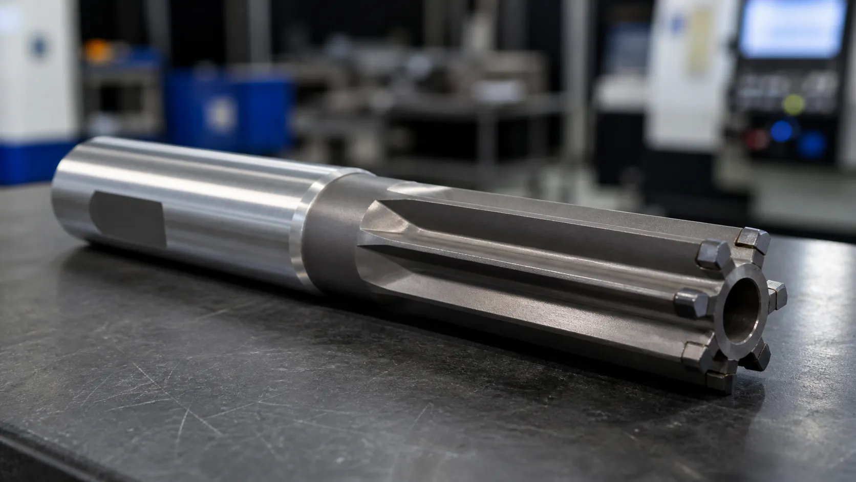
PCD tooling can be a strong fit for stable, repetitive aluminum machining and an expensive distraction in a cell with uncontrolled runout, changing stock, or an unsuitable workpiece. Before choosing PCD, ask one question: “Does this material, feature, process, and production volume give PCD a problem it can solve?”
Short answer: PCD tooling is best suited to stable, repetitive machining of aluminum, high-silicon aluminum, CFRP, graphite, and selected copper alloys where abrasive wear, dimensional drift, or frequent tool changes make carbide expensive. It is generally not the first choice for steels, cast irons, unstable setups, or frequently changing low-volume parts.
Not sure? Run the 3-minute PCD application self-check.
1. Quick Answer: When Is PCD Tooling a Good Fit?
PCD, or polycrystalline diamond, can provide a sharp edge and strong resistance to abrasive wear. Those properties create value only when the workpiece and machining system allow the edge to use them. For the CVD diamond alternative, see how PCD compares with CVD diamond tooling.
An application is worth evaluating when the material is technically suitable, the operation repeats in meaningful volume, wear creates measurable production cost, and the plant can approve the result against a controlled trial. Compare the complete cost per accepted part or hole; the purchase price of the tool is only one line in it.
Material is only the first gate. High-silicon cast aluminum behaves differently from wrought aluminum, while CFRP, copper, and graphite require different edge geometry and chip or dust control. Specify PCD when it solves a named production problem on the part.
2. PCD Tooling Application and Material Map
| Application | Typical materials | Common operations | Why PCD is considered | Main validation risk |
|---|---|---|---|---|
| Automotive and EV aluminum components | ADC12, A380, Al-Si and wrought aluminum | Reaming, boring, milling, combination machining | Abrasive wear, finish consistency and dimensional stability | Pre-hole variation, thin walls, runout and coolant |
| Precision aluminum housings | Cast and wrought aluminum | Bore finishing, step reaming, spot facing and profiling | Repeatable size, form and surface requirements | Clamping distortion and datum transfer |
| CFRP and GFRP parts | Carbon- and glass-fiber composites | Drilling, trimming, countersinking and reaming | High abrasiveness and edge-quality demands | Delamination, fiber pull-out, dust and stack transitions |
| Selected copper-alloy parts | Copper, brass and selected bronze grades | Turning, boring, drilling and reaming | Sharp-edge and low-friction potential | Smearing, adhesion and alloy variation |
| Graphite and filled polymers | Graphite, glass-filled plastics and abrasive laminates | Milling, drilling and profiling | Rapid carbide wear in abrasive material | Dust, chipping and edge geometry |
| Repetitive multi-feature parts | Suitable non-ferrous materials | Drill-ream, step, form and combination machining | Fewer tool changes and controlled feature relationships | Chip evacuation and incompatible cutting conditions |
Use this table to screen applications; it does not prescribe a tool. Final selection depends on the controlled drawing, material condition, incoming feature, machine system, acceptance criteria, and sample evidence.
Not sure whether your material and process justify PCD? Send the material grade, drawing, and current tool-life problem for an application review.
3. Best PCD Applications in Aluminum Machining
Aluminum machining is the most important PCD application family for XRZ customers because it connects suitable cutting material with high-volume, finish-critical parts. Relevant components include EV motor housings, transmission housings, valve bodies, compressor housings, cylinder heads, cylinder blocks, pumps, and bearing carriers.
High-silicon aluminum and abrasive wear
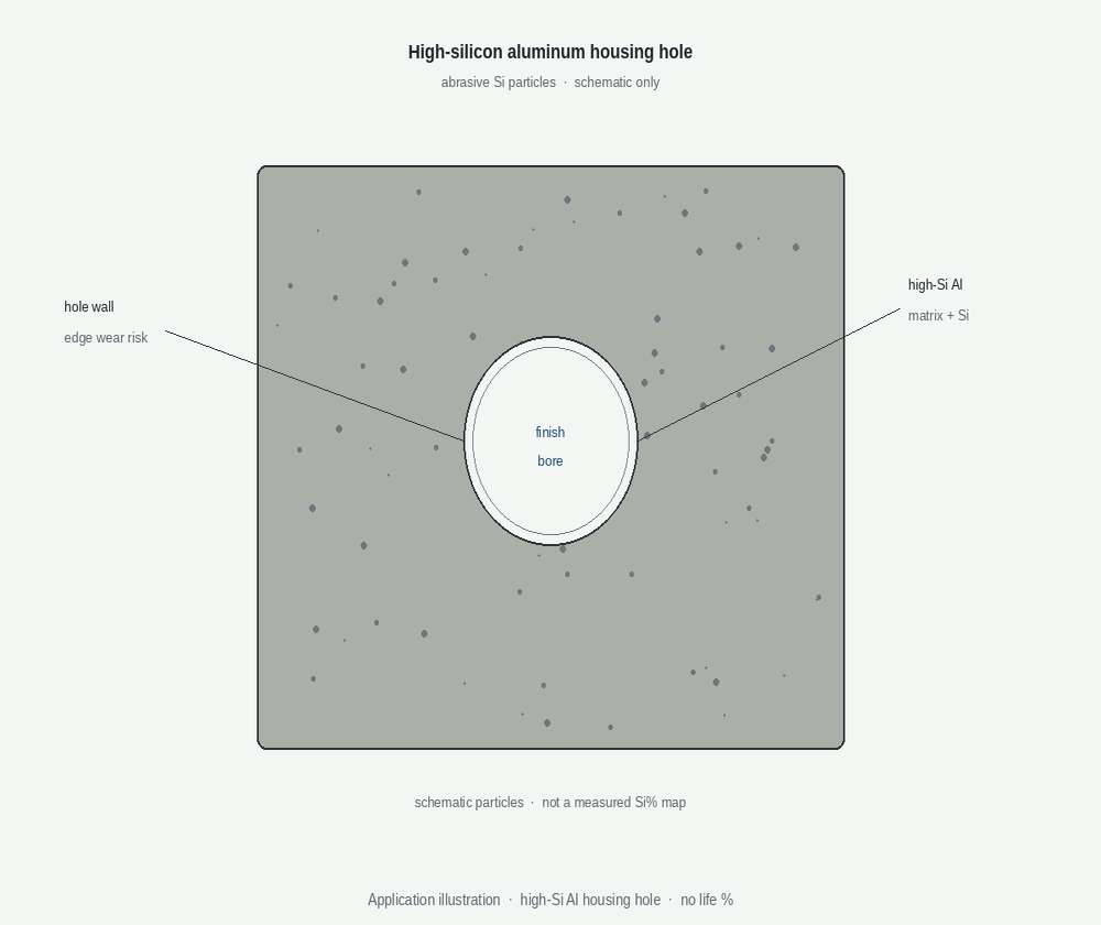
ADC12, A380, and other aluminum-silicon casting alloys can contain hard silicon particles that accelerate cutting-edge wear. When a stable carbide process gradually loses diameter control, surface consistency, or burr control as the edge wears, PCD may deserve evaluation.
Silicon content does not make PCD automatic. The review must distinguish abrasive wear from adhesion, built-up edge, chip recutting, excessive allowance, poor entry, or an unstable pre-hole. If the dominant failure is upstream of the cutting edge, changing the cutting material will not remove it.
Use the material certificate or verified alloy designation where possible. Then connect it to the observed failure:
- Does diameter drift correlate with edge wear?
- Does surface finish change progressively or fail randomly?
- Are offsets increasing because the tool wears, or because the machine and gauge disagree?
- Does the current edge show abrasion, adhesion, chipping, or mixed damage?
- Do different casting lots behave differently?
The aluminum silicon content guide explains how silicon, wear mode, process stability, and cost per accepted hole interact.
Automotive and EV aluminum housings
Housing parts often combine precision bores, bearing seats, valve bores, locating holes, seal faces, and stepped features. Thin walls and complex clamping can make the cutting tool appear responsible for errors created by distortion or datum transfer. A useful PCD review therefore covers the complete route, from the incoming feature and clamping to the final diameter.
Aluminum-specific risks include casting-lot variation, silicon-driven abrasion, adhesion or built-up edge, thin-wall distortion, cross holes, and chips trapped in blind or stepped features. Use actual pre-hole measurements and wear evidence to determine which of these is driving the rejected bore.
PCD can be evaluated for precision reaming, fine boring, face-related operations, profiling, and combination machining. The strongest business case normally appears when a released part family repeats often enough for wear-related corrections and changes to affect accepted production.
XRZ customer validation: ADC12 EV motor housing
In one customer-validated ADC12 EV motor-housing project, XRZ replaced the existing multi-tool route with a custom PCD combination reamer covering roughing, precision finishing, and chamfering. The customer ran the tool with 40 bar internal coolant and validated the result on its production equipment and inspection system.
| Project item | Existing process | Validated XRZ process |
|---|---|---|
| Tool concept | Previous multi-tool route | Custom PCD combination reamer |
| Tool life | 1,200 parts | 4,800 parts |
| Cycle time | 48 seconds | 22 seconds |
| Surface finish | Ra 0.8 μm | Ra 0.32 μm |
| Coolant | Customer baseline | Internal coolant, 40 bar |
These results belong to this specific ADC12 part, drawing, machine, fixture, pre-machining condition, coolant system, cutting data, and acceptance method. They are not a universal guarantee for other aluminum parts or PCD tools. A new application requires its own engineering review and sample validation.
Judge cost per accepted hole
A PCD tool may cost more to buy than a carbide alternative. Compare the complete production route:
- tool acquisition and reconditioning;
- usable life under the same end-of-life rule;
- planned and unplanned changes, offsets, and inspection;
- downtime, scrap, and rework;
- accepted holes or parts—not cycles started.
Do not import a generic “PCD lasts several times longer” multiplier into the calculation. Use plant data and a controlled trial. The XRZ cost-per-accepted-hole model provides a common framework for comparing routes without turning a quotation into a performance guarantee.
4. Precision Bore Finishing with PCD Reamers
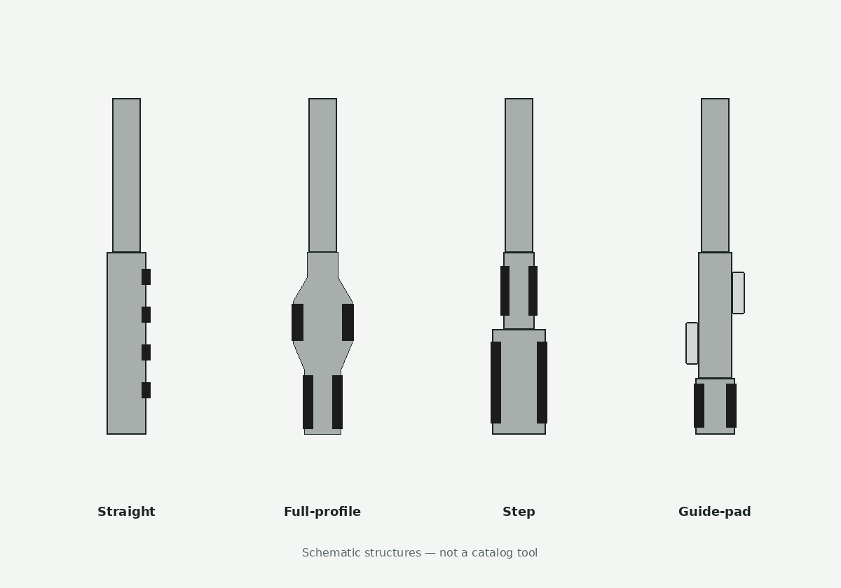
Precision bore finishing is XRZ's central PCD tooling application. The tool is designed around a defined hole: diameter, tolerance, depth, entry and the operation before it.
Depending on the feature and process route, the design may use straight, guided, stepped, form, blind-hole, or combination geometry.
The decision should begin with the finished feature and move backward:
- What must the accepted bore meet?
- What condition reaches the reaming operation?
- Which tool features control guidance, stock removal, coolant, and chip exit?
- How will the tool be inspected?
- How will the customer validate the bore and release the revision?
Keep three types of evidence separate:
- Tool inspection: confirms specified reamer characteristics under a stated measurement method.
- Sample machining: records performance on the customer's workpiece and machine.
- Production release: confirms that the approved revision and conditions can be repeated over the agreed run.
An inspection report confirms the tool characteristics measured under its stated method; finished-bore capability still requires a customer-side trial. Review the PCD tools precision-reaming guide, then evaluate an XRZ custom PCD reamer and define acceptance through the XRZ validation process.
5. PCD Combination Tools for Repetitive Production
PCD combination tools can consolidate drilling, reaming, spot facing, boring, chamfering, or multiple diameters when several features share a datum and repeat in sufficient volume. Their value comes from controlling related features and cutting avoidable tool changes; extra steps that do neither only add regrind cost and risk.
A drill-reamer or multi-step concept is worth evaluating when:
- the drawing and process route are stable;
- one machine and fixture can support the sequence;
- chip evacuation and cutting conditions work for every section;
- inspection can verify every critical feature;
- accepted-part economics justify the added replacement risk.
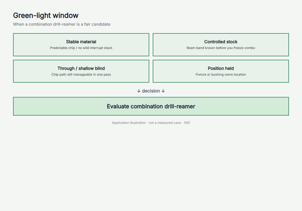
Illustration: a decision chart for when a combination drill-reamer is a fair candidate. Four conditions (stable material, controlled stock, a through or shallow blind hole, and position held by a fixture or bushing) lead to the step "Evaluate combination drill-reamer".
Separate tools are often better when drilling and finishing need conflicting conditions, the create-hole operation cannot hold location, one section will wear much earlier, or revisions change frequently.
Combining operations still requires clear ownership of hole creation, finishing, and failure diagnosis. Such integration is feasible, but that does not make it economical for every part. For drawing-based integrated holemaking, review the XRZ custom PCD combination drill-reamer.
6. Other Suitable Materials: CFRP, Copper and Graphite
CFRP, GFRP, and composite stacks
Carbon- and glass-fiber composites are abrasive and can fail through delamination, fiber pull-out, exit damage, and heat. Do not group panels, honeycomb structures, CFRP/aluminum stacks, and CFRP/titanium stacks under one recommendation; each changes edge load, dust or chip behavior, and exit conditions. PCD concepts differ for CFRP and for stacks, which illustrates why geometry must follow the material system. See PCD tools for CFRP machining challenges.
Copper and brass
PCD may support selected copper, brass, and bronze operations, but alloy behavior varies. Copper may smear or adhere; brass ranges from free-cutting grades to low-lead compositions. Carbide may remain more economical for short runs or forgiving tolerances. Review the copper and brass PCD reaming boundaries.
Graphite and filled polymers
Graphite, filled plastics, and abrasive laminates can wear conventional edges quickly. PCD may be evaluated when that wear changes dimensions or edge quality, while dust extraction, machine protection, and entry or exit damage remain controlled.
7. When Not to Use PCD Tooling
Iron-based workpieces
PCD is generally not the first choice for steels and cast irons. At machining temperature, the interaction between diamond carbon and iron can accelerate chemical wear. Polycrystalline cubic boron nitride (PCBN), carbide, cermet, or ceramic may be more appropriate depending on workpiece hardness, interruption, finish, and production conditions.
Low-volume or frequently changing parts
Carbide may be the better commercial choice when annual volume is low, the drawing changes often, several unrelated jobs must share one tool, or the process route is not frozen. PCD becomes attractive only when its application benefit outweighs engineering, validation, inventory, and service cost.
Unstable machining systems
Do not use PCD to hide excessive runout, weak fixturing, inconsistent incoming stock, poor coolant delivery, chip recutting, or gauge disagreement. Correct the unstable input first. Otherwise, a more expensive edge may fail for the same reason as the current tool.
Severe impact or uncontrolled interruption
PCD is hard and wear resistant, but the edge can still be damaged by vibration, impact, interrupted entry, or recut chips. Review edge support, tool approach, machine dynamics, entry geometry, and the actual interruption before release.
8. PCD vs Carbide vs PCBN
| Cutting material | Typical application direction | Main selection advantage | Important limitation |
|---|---|---|---|
| PCD | Suitable non-ferrous metals, composites, and abrasive non-metals | Wear resistance and sharp-edge potential | Generally unsuitable for iron-based workpieces |
| Carbide | Broad material range, changing work, low-to-medium volume, and general operations | Flexibility, availability, and lower entry cost | May wear faster in highly abrasive repeat production |
| PCBN | Hardened steels, cast irons, and selected iron-based applications | Chemical and thermal suitability for ferrous hard machining | Does not replace PCD or carbide in every operation |
This is a starting boundary. PCD grain, PCBN grade, carbide substrate or coating, edge preparation, geometry, process stability, and acceptance criteria still determine the tool. For bore finishing, continue with PCD reamer vs carbide reamer.
9. Application Evaluation Checklist
Before requesting a PCD proposal, confirm that the application pack identifies:
- controlled drawing and revision;
- exact material grade, condition, silicon content, or composite layup;
- operation and feature sequence;
- finished requirements and actual incoming condition;
- machine, spindle interface, holder, stickout, and runout;
- coolant, filtration, dust extraction, and chip path;
- current tool, cutting data, wear evidence, and scrap mode;
- volume, lot size, and change frequency;
- inspection method, sample objective, and release authority;
- repeat-order and reconditioning expectations.
Define one trial question. “Can the controlled setup hold the specified bore through the agreed sample?” is testable. “Try PCD and see whether it lasts longer” is not.
10. What Distributors and OEM Buyers Should Confirm Before Quoting PCD Tooling
Distributor and OEM projects add commercial handoffs. Confirm these points before quoting:
- Who controls the drawing, revision history, and confidential application data?
- Who defines the sample plan, runs the trial, and approves production?
- Which inspection documents accompany samples and repeat orders?
- Are private-label marking, packaging, or certificates required?
- How are repeat orders, reconditioning, and failure reviews routed?
- Who owns final cutting parameters and end-user production approval?
Record the answers in the quotation and project handoff. See how distributors evaluate a PCD reamer manufacturer for the fuller framework.
11. How XRZ Reviews a PCD Tooling Project
XRZ is a manufacturer of drawing-based custom PCD reamers and combination holemaking tools for suitable aluminum and precision-bore applications. Its supply scope includes straight, guided, stepped, form, combination, and drill-reamer configurations developed against the customer's feature and process requirements.
The first review identifies the finished feature, material, incoming condition, machine system, production problem, and acceptance method. If PCD is technically and commercially reasonable, XRZ can develop a controlled tool concept for manufacture, inspection, customer trial, revision, and repeat supply.
XRZ does not treat PCD as the default answer for every material. If the evidence points toward carbide, PCBN, separate operations, or a process correction, that boundary should be identified before the custom tool is frozen.
Send Your Drawing for Application Review, or View the PCD Reamer RFQ Checklist before preparing the inquiry.
12. Frequently Asked Questions
What materials are most suitable for PCD tooling?
PCD is commonly evaluated for suitable aluminum and copper alloys, CFRP, GFRP, graphite, and filled polymers. The exact grade, operation, machining system, failure mechanism, and economics still decide.
Is PCD tooling suitable for steel or cast iron?
PCD is generally avoided for iron-based workpieces because diamond carbon can react with iron at machining temperature. Carbide, cermet, ceramic, or PCBN may be more suitable.
When is PCD better than carbide for aluminum?
Evaluate PCD when a stable aluminum process has repeatable wear-related cost such as diameter drift, frequent offsets, tool changes, or scrap. Carbide may remain better for short runs, changing work, or unstable setups.
Can PCD tools machine CFRP and composite stacks?
Yes, but a CFRP panel, CFRP/aluminum stack, and CFRP/titanium stack require different geometry, sequence, dust or chip control, and validation.
Is PCD tooling economical for low-volume production?
Sometimes, but low volume weakens the case. Compare engineering, validation, changes, scrap, inspection, and accepted-part cost before choosing PCD.
What information is needed for a custom PCD tooling quotation?
Provide the drawing, material, pre-hole or stock, finished requirements, machine and holder, coolant or dust control, current failure evidence, volume, inspection method, and trial objective.
Author: Kevin Zeng, CEO
Engineering reviewed by: Jiack Liu, Engineering Director
Review status: Approved for publication
Review date: September 22, 2026