
Start with cutting speed and feed recommendations for the exact tool, material and operation. Calculate spindle speed and feed rate, then check tool engagement, machine limits and chip evacuation before validating the settings on the part.
The calculations connect the variables. They do not establish whether a particular cutting speed, chip load or depth of cut is suitable for your setup.
This guide focuses on end milling, including peripheral milling, slotting and pocketing. Drilling and reaming use a different feed basis; see carbide drill speeds and feeds for holemaking process-first guidance. The worked example uses hypothetical teaching inputs to demonstrate arithmetic; it is not an HENTRY cutting-data recommendation.
Before calculating, follow five steps:
- Identify the operation: distinguish side milling, full slotting, pocketing and holemaking.
- Confirm the inputs: record the material, tool, cutting diameter, effective teeth, engagement and coolant conditions.
- Calculate RPM and feed: keep the units consistent.
- Check the limits: review the tool assembly, machine, toolpath and chip exit route.
- Validate the result: inspect the part and cutting edges, then document any changes.
Definitions · Calculate · Chip thinning · Example · Limits & evacuation · Validate · FAQ
What Do Cutting Speed, Spindle Speed and Feed Rate Mean?
Cutting speed is not spindle speed
Cutting speed describes the peripheral speed at the cutting diameter. It is commonly expressed in metres per minute or surface feet per minute.
Spindle speed describes how many revolutions the tool makes per minute.
At the same cutting speed, a smaller cutting diameter requires a higher RPM. For tools whose effective cutting diameter changes with the contact position, the nominal outside diameter may not be the correct value to use.
Feed per tooth is not feed per revolution
The feed terms describe different quantities:
| Parameter | Symbol | Common units |
|---|---|---|
| Cutting speed | vc | m/min or SFM |
| Spindle speed | n | RPM |
| Feed per tooth | fz | mm/tooth or IPT |
| Feed per revolution | fn | mm/rev or IPR |
| Feed rate | vf | mm/min or IPM |
| Effective number of teeth | zc | Dimensionless count |
For a conventional end mill, the feed calculation uses the effective teeth that contribute to the cut over each revolution. Do not substitute the number of teeth touching the workpiece at one instant. Metric milling variable definitions are documented in this milling formulas reference (metric PDF) and this milling formulas and definitions overview.
Chip load is not always chip thickness
In milling, chip load commonly refers to feed per tooth. Maximum undeformed chip thickness is a separate geometric quantity.
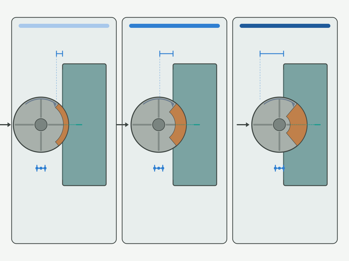
The relationship changes with engagement and cutting-edge geometry. This distinction matters when considering chip thinning: the programmed feed per tooth can remain unchanged while the maximum chip thickness decreases. This chip-thinning guide explicitly distinguishes these quantities. A complementary explanation appears in this chip thinning overview.
The thickness of a collected, deformed chip should not be treated as a direct substitute for the undeformed chip thickness used in the cutting model.
How Do You Calculate Spindle Speed and Feed Rate?
Cutting speed formula and RPM calculation
For metric inputs:
n = (1000 × vc) / (π × D)
Where:
- n = spindle speed in RPM;
- vc = cutting speed in m/min;
- D = applicable cutting diameter in mm.
To calculate cutting speed from an existing spindle speed:
vc = (π × D × n) / 1000
For imperial inputs:
n = (12 × SFM) / (π × Dinch)
Keep the unit systems separate. A diameter entered in inches cannot be used in the metric equation without conversion. A practical speeds-and-feeds orientation is also summarized in this speeds and feeds 101 overview.
Feed rate calculation for milling
Once spindle speed and feed per tooth are selected:
vf = n × zc × fz
With fz in mm/tooth, the result is mm/min. With feed per tooth in inches, the result is inches per minute.
You can also check an existing program by rearranging the equation:
fz = vf / (n × zc)
Interactive milling calculators can help check arithmetic after you select inputs; they do not replace application limits. See this milling calculator set as one third-party check tool.
Use the correct feed basis for drilling and reaming
When the applicable tool data specifies feed per revolution:
vf = n × fn
Do not multiply a published feed-per-revolution value by the flute count again. This drilling formulas and definitions page distinguishes feed per revolution from feed speed.
For reaming, follow the feed basis stated in the specific tool documentation. Check that the CNC program’s feed mode and units match the intended calculation. Aluminium PCD reamer starting-data literacy stays on PCD reamer cutting speed and feed for aluminium. Reaming process context lives on what is reaming machining.
Recalculate feed when RPM changes
If the calculated RPM exceeds the permitted speed of the machine or tool assembly, select an allowable operating speed first.
Then calculate feed from that actual RPM. Keeping the original feed rate while reducing RPM increases the calculated feed per tooth.
Maintaining feed per tooth does not preserve every aspect of the process: cutting speed has also changed, so the revised settings still require validation.
Chip Thinning and Engagement
The formulas require selected inputs. They do not generate suitable starting values from the material name alone.
Start with the exact material and tool
Use recommendations that identify the relevant material grade and condition; tool series, diameter, geometry and coating; roughing or finishing operation; axial and radial engagement; and coolant or lubrication conditions.
A generic “steel” or “aluminium” entry may omit differences that affect the recommendation. Similarly, data for one manufacturer’s tool should not be presented as validated data for an HENTRY tool.
Record whether the recommended feed is a conventional feed-per-tooth value, a target chip-thickness value or an already adjusted value for a specified engagement. After the end-mill profile and flute path are already justified, product families to check include carbide end mills and square end mills. Broader milling-tool literacy stays on milling tools guide.
Check axial and radial engagement
Two dimensions must remain visible in the setup record:
- Axial depth of cut, ap: engagement along the tool axis.
- Radial engagement, ae: engagement across the cutter.
A feed calculated for a light peripheral cut should not automatically be transferred to full slotting. The tool encounters different engagement and chip-clearance conditions.
For changing toolpaths, check the local condition rather than relying only on the nominal stepover. Entries, corners and remaining stock may create conditions that differ from a straight pass. When entry strategy limits the cut, see ramping and helical entry for end mills.
| Check | Side milling (partial ae) | Full slotting |
|---|---|---|
| Radial engagement | Often below half diameter; chip thinning may apply | Near full diameter; do not assume side-mill feed |
| Chip exit route | Open wall may allow easier exit | Closed slot retains chips more easily |
| Feed definition | Confirm if recommendation already compensated | Prefer slotting-specific guidance |
| Validation focus | Load, finish on wall, local corners | Retention, heat, exit packing |
Understand the applicable chip-thinning geometry
In the conventional peripheral-milling model described in the chip-thinning guide linked above, maximum chip thickness decreases as radial engagement falls below half the cutter diameter, while feed per tooth remains constant.
Within that model, a feed adjustment can be used to maintain a selected maximum chip thickness. This is a geometry-based adjustment, not permission to increase feed without checking the tool and setup. If a published radial-thinning equation is required for a particular geometry and no matching public page is on file for this draft, treat the numeric compensation as [NEEDS VERIFICATION] against the tool supplier’s model before production use.
Check whether compensation has already been applied
Before applying another adjustment, ask:
- Does the tool supplier’s recommendation already account for the stated radial engagement?
- Is the input a target chip thickness or a compensated feed per tooth?
- Has the CAM system already adjusted the feed?
- Does the engagement remain within the assumed range throughout the cut?
Applying compensation twice can produce an unintended feed command.
Know where the simple model stops
Do not extend a simple peripheral-milling correction directly to ball-nose tools with changing contact positions; round inserts or other entering-angle geometries; full-slot cutting; entries and corners with changing engagement; or toolpaths whose local feed differs from the straight-line assumption.
These situations need the applicable geometry model and tool guidance. Chip-thinning compensation also does not resolve inadequate workholding, excessive runout or blocked chip evacuation. Tool-assembly stiffness and holder reach belong in the limit check; see this toolholding overview.
Worked Example: Calculate, Limit and Recheck the Parameters
The following values are hypothetical teaching inputs. They demonstrate arithmetic and are not recommended settings for a material or tool. They are not HENTRY cutting data.
| Input | Assumed value (hypothetical) |
|---|---|
| Cutting diameter | 10 mm |
| Effective teeth | 4 |
| Cutting speed | 120 m/min |
| Feed per tooth | 0.03 mm/tooth |
| Available operating-speed limit in this example | 3,000 RPM |
Step 1: Calculate the theoretical spindle speed
n = (1000 × 120) / (π × 10) ≈ 3,820 RPM
Step 2: Calculate the corresponding feed rate
vf ≈ 3,820 × 4 × 0.03 ≈ 458 mm/min
Step 3: Recalculate at the available RPM
The example limits operation to 3,000 RPM. To retain the assumed feed per tooth:
vf = 3,000 × 4 × 0.03 = 360 mm/min
The resulting cutting speed is:
vc = (π × 10 × 3,000) / 1000 ≈ 94.2 m/min
| Calculated quantity | Theoretical setting | At the example speed limit |
|---|---|---|
| Spindle speed | Approximately 3,820 RPM | 3,000 RPM |
| Feed rate | Approximately 458 mm/min | 360 mm/min |
| Feed per tooth | 0.03 mm/tooth | 0.03 mm/tooth |
| Cutting speed | 120 m/min | Approximately 94.2 m/min |
If the original feed of approximately 458 mm/min were retained at 3,000 RPM, feed per tooth would rise to approximately 0.0382 mm/tooth.
Step 4: Identify what remains unverified
The arithmetic has not established whether the assumed cutting speed and feed suit the actual material; whether the tool can operate at the intended engagement; whether chip-thinning compensation is applicable; whether the machine and workholding are adequate; or whether chip evacuation and finished-part quality are acceptable.
Those questions require application-specific information and a controlled validation run.
Limits, Chip Evacuation and Validation Checklist
A calculated feed rate says how quickly the tool advances. It does not describe where the chips go after they leave the cutting edge.
Distinguish three questions:
- Formation: what cutting conditions produced the chip?
- Evacuation: can the chip leave the cutting zone?
- Re-cutting: does the chip remain where another edge will encounter it?
This milling troubleshooting overview separates chip jamming from re-cutting and identifies slotting and pocketing as relevant situations. A parallel process tip set is in this milling troubleshooting guide. Chip-formation literacy that stays independent of a single brand catalogue includes this chip control overview. Broader milling process structure is summarized on this milling knowledge hub.

Follow the chip path before changing parameters
For a slot or pocket, use this inspection sequence:
- Identify where chips collect.
- Check whether the intended coolant or evacuation method reaches that location.
- Inspect the available space and exit route.
- Review whether the toolpath repeatedly carries the cutter through retained chips.
- Compare the tool geometry and current parameters with the applicable recommendations.
Choose the evacuation method to suit the material, tool and machine provisions. Do not prescribe air, flood coolant or dry cutting as a universal solution. Coolant-system education that stays at method level includes this coolant know-how overview. For drilling-specific packing symptoms, use carbide drill chip packing checklist; for chip appearance literacy in holemaking, see drilling chip shapes and colors.
Chip appearance is useful supporting evidence, but a photograph alone is not a complete diagnosis. Record the material, coolant conditions, tool state and location where the chips were collected.
What should you check before changing speed or feed?
Use the symptom to select the next check. Avoid changing several unrelated variables without recording what changed.
| Observation | First check | Next action |
|---|---|---|
| Calculated RPM exceeds an operating limit | Machine and tool-assembly documentation | Select an allowable RPM and recalculate feed and cutting speed |
| Low-radial-engagement cut appears underloaded | Feed definition, existing compensation and engagement | Determine whether a suitable chip-thickness adjustment is needed |
| Chips accumulate in a pocket | Chip exit route and evacuation access | Address retention, then reassess parameters |
| A problem occurs mainly in corners | Local engagement, remaining stock and programmed feed | Review the affected toolpath segment |
| Finish or dimensions drift during the run | Tool condition, thermal state, runout and support | Record the trend and investigate the changing condition |
| Vibration appears | Workholding, projection, holder and engagement | Follow a structured stability check before changing parameters |
Stop the trial if the tool shows abnormal damage or the setup becomes unstable. Do not continue increasing parameters to see whether the problem disappears. Symptom triage that is already a broader fault problem stays on CNC machining troubleshooting. Surface-quality checks after parameter changes can use machining surface finish.
Validate against the part requirements
Agree the acceptance criteria before testing. Depending on the component, these may include dimensions, surface finish, burr condition and an agreed tool-wear criterion.
Use a record such as the following:
| Record group | Information to retain |
|---|---|
| Workpiece | Material grade, condition, feature and quality requirements |
| Tool assembly | Tool identification, diameter, teeth, holder and projection |
| Cutting settings | RPM, feed, calculated feed per tooth, ap and ae |
| Process conditions | Toolpath, coolant method and relevant machine limits |
| Observations | Chip retention, abnormal load behaviour, vibration and edge condition |
| Results | Measurements, acceptance decision and reason for the next change |
A successful first pass establishes a result under those recorded conditions. Further checks are needed before treating the settings as a stable production process. Selection-stage inputs before parameter work are organized in the cutting tool selection handbook.
What Information Is Needed for Tool Selection and Parameter Review?
A useful enquiry includes more than a requested RPM and feed.
- Workpiece and quality: material grade and condition; feature dimensions and accessibility; tolerance, surface and burr requirements; batch size and production stage.
- Tool and machine setup: current tool identification, diameter, flute count and coating; holder, projection and workholding; machine and available operating-speed range; coolant or lubrication arrangement.
- Current process and problem: RPM, feed, axial depth and radial engagement; toolpath type and the location where the problem occurs; relevant chip, cutting-edge and workpiece photographs; inspection results and the current tool-change criterion.
This information helps distinguish a calculation issue from a tool-selection, setup or evacuation issue. When a solid carbide drilling path is already justified separately, check solid carbide drills rather than transferring milling fz directly.
Discuss Tool Selection with HENTRY
When evaluating an HENTRY cutting tool, provide the drawing and current process conditions together. Include the material, feature dimensions, quality targets, machine setup and existing parameters.
The relevant next step is to match a candidate tool to the operation and establish which starting data and validation checks apply. Any proposed geometry, coating or parameter range should be tied to the actual tool specification. No price, MOQ or unverified lead time is stated here.
Send drawing + current cutting parameters
Suggested enquiry subject: Tool selection and cutting-parameter review - [material] - [operation]
If a problem occurs only in one section of the toolpath, identify that section. A marked drawing or clear description can be more useful than a general report of “poor tool life.”
Speeds, Feeds and Chip Control FAQ
How do I calculate feed rate from chip load?
For conventional milling, multiply spindle speed by the effective number of teeth and feed per tooth: vf = n × zc × fz. Check whether the supplied chip-load value already includes an engagement adjustment before applying any additional compensation.
Should I reduce feed rate when I reduce RPM?
If the intention is to maintain the same feed per tooth, calculate the new feed using the reduced RPM. Keeping feed unchanged increases feed per tooth. The lower cutting speed must also be assessed for the actual application.
Is chip load the same as chip thickness?
Not in every cutting condition. Chip load commonly means feed per tooth, while undeformed chip thickness also depends on engagement and geometry. The distinction is central to radial chip thinning.
Can I use the same settings for slotting and side milling?
Do not assume that settings transfer unchanged. Full slotting and partial radial engagement differ in tool contact and chip-clearance conditions. Use guidance for the actual operation and validate the result.
When does the guidance in this article not apply directly?
The basic calculations do not supply material-specific starting parameters. Simple peripheral-milling assumptions also require adaptation for ball-nose tools, special geometries, changing engagement and other operations. Drilling and reaming must use the feed basis stated in their own tool data.
What information is missing from a reliable parameter recommendation?
Material condition, exact tool specification, engagement, projection, workholding and coolant conditions are common missing inputs. A parameter recommendation also needs a defined quality target and a way to judge the result.
How are the settings confirmed on my part?
Machine representative features under recorded conditions, inspect the required characteristics and examine the tool. Document changes and repeat the checks across the conditions relevant to production. Do not treat one acceptable part as proof of stable tool life or repeatability.
Sources and Related Parameter Tasks
The outbound references support formula definitions, chip-thinning geometry, milling troubleshooting and coolant-method literacy cited in the body. Manufacturer-specific data remain tied to their own products. The worked example and checklists are HENTRY editorial teaching aids, not measured performance results. Sources checked for this draft on 20 October 2026 (Asia/Shanghai).
- Milling formulas reference, metric PDF (third-party education PDF; linked in body)
- Milling formulas and definitions overview (third-party education page; linked in body)
- Chip-thinning guide (third-party education page; linked in body)
- Chip thinning overview (third-party education page; linked in body)
- Speeds and feeds 101 overview (third-party education page; linked in body)
- Milling calculator set (third-party calculator hub; linked in body)
- Drilling formulas and definitions page (third-party education page; linked in body)
- Toolholding overview (third-party education page; linked in body)
- Milling troubleshooting overview (third-party education page; linked in body)
- Milling troubleshooting guide (third-party education page; linked in body)
- Chip control overview (third-party education page; linked in body)
- Milling knowledge hub (third-party education hub; linked in body)
- Coolant know-how overview (third-party education page; linked in body)
- CIRP scientific research portal (third-party research society; CIRP portal)
- NIST Engineering Laboratory (public metrology / manufacturing research entry; NIST EL)
- Cutting data and application notes portal (third-party tooling education; cutting data notes portal)
For drilling speeds and feeds OWN, use carbide drill speeds and feeds. For end-mill selection after parameters are framed, return to the cutting tool selection handbook and milling tools guide.