
A smoother surface does not automatically mean a more accurate part. Start with the drawing requirement, confirm how the surface is measured, and assess finish, size, and form separately before you change the machining process.
Surface roughness, size, and shape are different acceptance items. An Ra or Rz reading has full meaning only with the parameter definition, the referenced standard, and the measurement conditions. After you improve finish, recheck diameter or other sizes, applicable form, and any functional requirement the print names. This HENTRY guide owns drawing-to-measurement-to-turning-or-reaming improvement and joint acceptance. Symptom triage for breakage, chatter, burrs, and size faults stays on the sibling CNC machining troubleshooting hub. Milling texture is noted briefly; grinding, honing, and lapping encyclopedias are out of scope.
Surface finish chart · Ra vs Rz · Measurement · Turning · Reaming · Validation
What Does Surface Finish Tell You, and What Does It Not Tell You?
Surface finish language on a print describes texture features under named methods. It does not replace size, form, or position. Treat photos and “looks shiny” comments as clues, not as acceptance.
Separate Roughness, Waviness, Lay and Local Defects
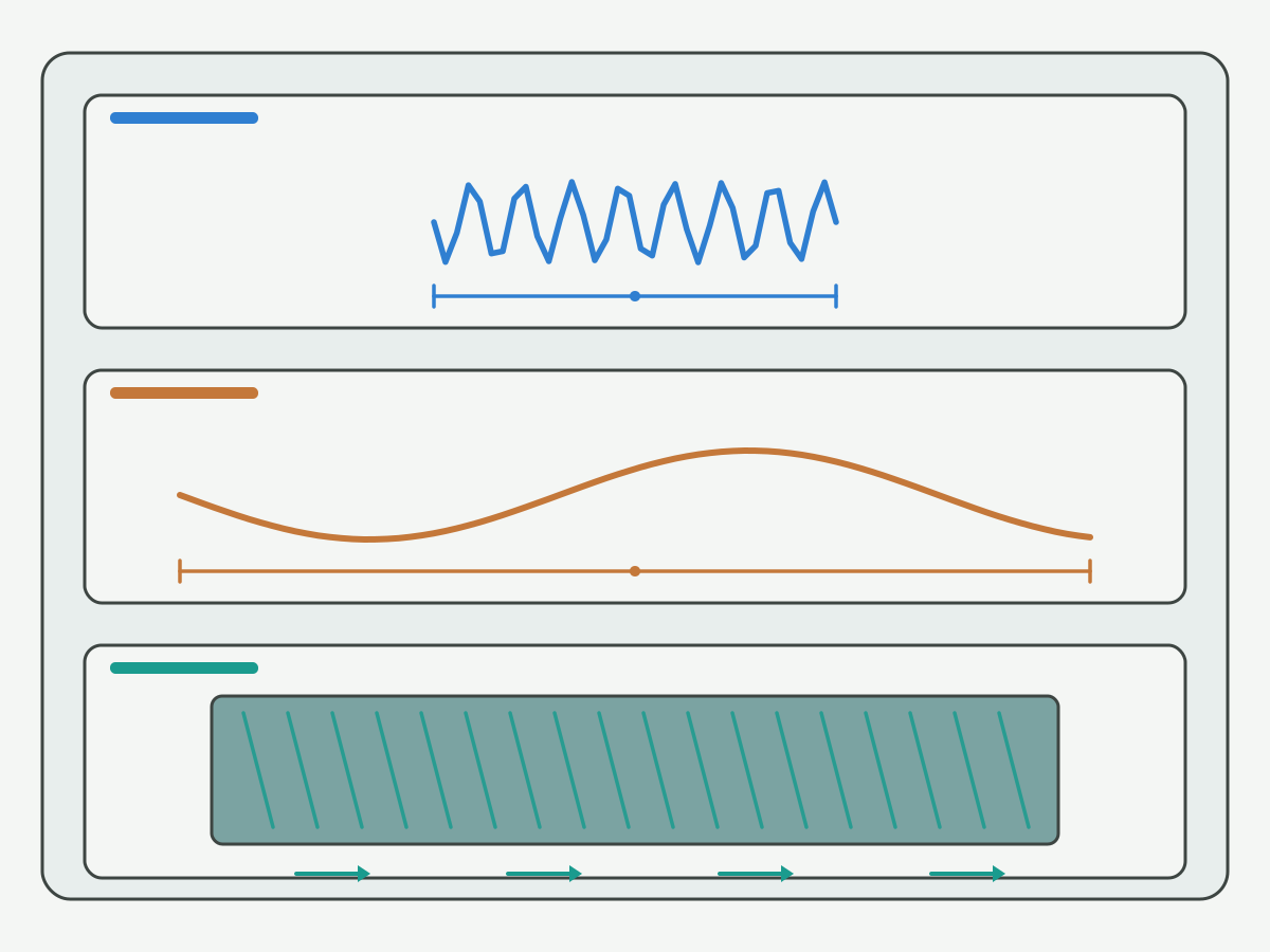
Roughness covers the fine-scale profile features assessed under the stated method and filter. Waviness covers longer-wavelength components assessed separately from roughness. Lay is the dominant direction of the machining texture. Local defects include scratches, pull-outs, pits, and tears that may sit outside the roughness parameter you are averaging. These distinctions depend on scale, filtering, and method. A magnified photo alone does not decide which family you are looking at. Profile parameter terms and definitions for profile methods are set out in the current ISO profile surface texture parameter standard. Areal (area-based) parameters belong to a different document family; do not treat Ra as identical to Sa. See the current ISO areal surface texture parameter standard when the print or method calls for areal evaluation.
Separate Surface Texture from Size, Form and Position
Use this checklist when a traveler mixes “finish” with “accuracy” language:
| Quality requirement | Question it answers | Do not substitute with |
|---|---|---|
| Surface roughness | Does the named parameter meet the limit under the stated method? | Visual shine alone |
| Size | Are diameter, length, or other sizes inside the stated limits? | An Ra or Rz reading |
| Form | Do roundness, cylindricity, flatness, or other form calls pass? | A single local size |
| Position | Is the feature located correctly to its datums? | A good surface appearance |
| Function | Do sealing, friction, fit, or coating needs pass? | One roughness number alone |
Start with the Functional Requirement
Surfaces may serve sealing, sliding or lubrication, fit and location, fatigue-sensitive zones, or later coating and bonding. Do not assign a universal Ra value to each function on this page. “Lower is always better” is not a selection rule. Read the drawing, the acceptance plan, and the function note first, then choose the parameter and method that can be compared across shifts and labs.
How Do You Read a Surface Finish Chart?
Many searches for a surface finish chart want a quick decode of symbols, units, and process starting points. Keep three table types separate: parameter meaning, unit conversion inside one parameter, and process capability notes that are only starting points until your shop proves them.
Confirm Parameter and Unit Before the Number
Write the parameter name (for example Ra or Rz), the unit, the limit type (max, band, or other), and the standard or company method referenced on the print. A number without those fields is not comparable. Educational overviews of common roughness parameters and how instruments present them (method classes and bandwidth limits) are summarized in this NIST introduction to surface finish metrology and this longer NIST surface finish metrology tutorial.
| What you see on a chart or print | What to record | Common shop mistake |
|---|---|---|
| Ra 1.6 | Parameter Ra, unit (µm or µin), limit type, standard/method | Assuming every “1.6” means the same unit and filter |
| Rz callout | Rz definition family in use, unit, evaluation settings | Treating Rz as a fixed multiple of Ra |
| Process column (turning, reaming, …) | Label as starting-point guidance only | Reading a process column as a capability guarantee |
| Symbol without text | Ask engineering for the expanded requirement | Guessing parameter from habit |
Use Unit Conversion Only Inside the Same Parameter
Convert micrometres to microinches only for the same parameter. A common exact factor is 1 µm = 39.37 µin; many shops round for traveler convenience and must write the rounding rule beside the number. Example for discussion only: Ra 1.6 µm is about Ra 63 µin when rounded to whole microinches. Do not convert Ra into Rz with any fixed factor.
| Same-parameter example | µm | µin (39.37×, then round per your rule) |
|---|---|---|
| Ra example A | 0.8 | ~32 |
| Ra example B | 1.6 | ~63 |
| Ra example C | 3.2 | ~126 |
These rows are unit examples, not HENTRY process capability claims and not acceptance limits for any HENTRY tool.
Why Process Charts Are Only a Starting Point
Process columns on public charts often list typical ranges seen in textbooks or catalogs. They omit your machine stiffness, tool condition, material lot, coolant, and measurement method. Use them to open a discussion, then prove the surface on your part under recorded settings. Do not publish an unverified “this process always reaches this Ra” table on this page.
Ra vs Rz: What Is the Difference?
Ra and Rz are both profile roughness parameters, but they weight the profile differently. Mixing them without stating definitions creates false disagreements between suppliers and labs.
What Ra and Rz Describe
Ra is an average roughness amplitude over the evaluation under the stated filter and length settings. Rz family parameters emphasize peak-to-valley character within sampling lengths (exact definition depends on the referenced standard edition). Specification operators for profile methods, including how filtering and evaluation are applied, are covered in the current ISO profile surface texture specification operators standard. Parameter education pages that list common profile parameters side by side (for instrument UI literacy, not as HENTRY acceptance) include this profile roughness parameter overview.
Can Ra Be Converted to Rz?
There is no universal fixed conversion factor that holds across materials, processes, filters, and evaluation lengths. Empirical ratios seen in one shop lot do not transfer to another process. If a print switches from Ra to Rz, treat it as a new requirement: update the method, the instrument setup, and the acceptance record. Keep areal parameters (for example Sa) in the areal document family; Ra is not Sa.
Why Similar Ra Values Can Hide Different Surfaces
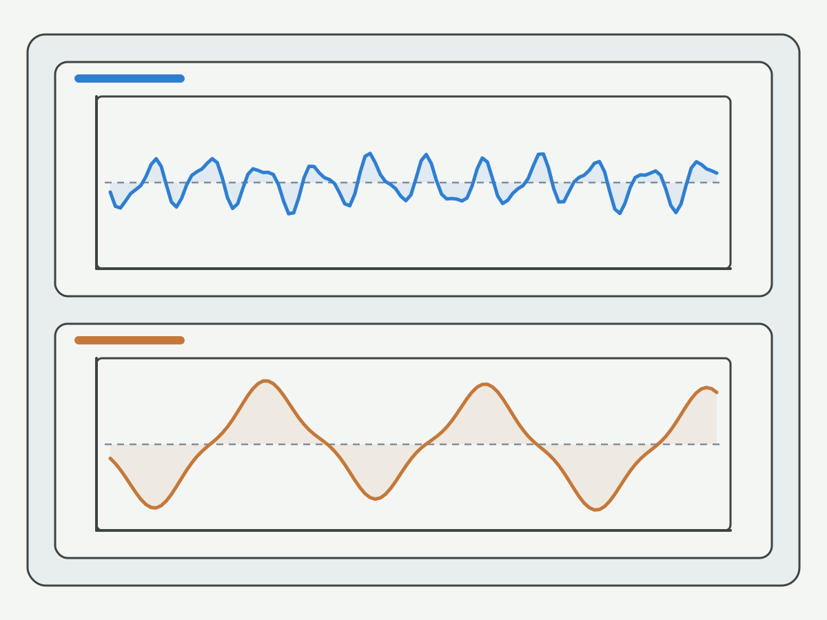
Two profiles can share a similar average height while one carries sharp peaks, deep valleys, or different skew. Function (sealing, fatigue, coating) may care about those shapes even when Ra looks acceptable. Keep raw profiles or traceable measurement files when the function is sensitive. National metrology work on surface texture methods, calibrations, and uncertainty context is summarized on this NIST surface texture metrology project overview.
How Should Surface Roughness Be Measured?
Comparable measurement is the bridge between a drawing callout and a process change. If two readings disagree, fix the measurement story before you grind a new feed into the program.
Read the Drawing Standard and Method First
Confirm the parameter, unit, limit, and any referenced standard or company procedure. Note whether the callout is profile or areal. If the print is silent on method, escalate to engineering instead of inventing a habit-based setup. A practical good-practice discussion of sampling length, evaluation length, and traverse length for stylus work is available in this NPL surface texture good practice guide (PDF). Use it to name the fields you must record; numeric defaults still follow the standard edition and instrument approval on your job.
Access the Real Surface
Contact stylus profiling and suitable optical methods both appear in shops. Outer diameters and open flats are usually easier to reach than deep bores, stepped holes, or interrupted walls. Probe interference, aperture limits, and reflectivity all change what you can trust. Do not treat contact and optical results as interchangeable by default. Method classification and bandwidth thinking are discussed in this NIST surface finish metrology methods paper (PDF).
Control Direction, Filtering and Evaluation Settings
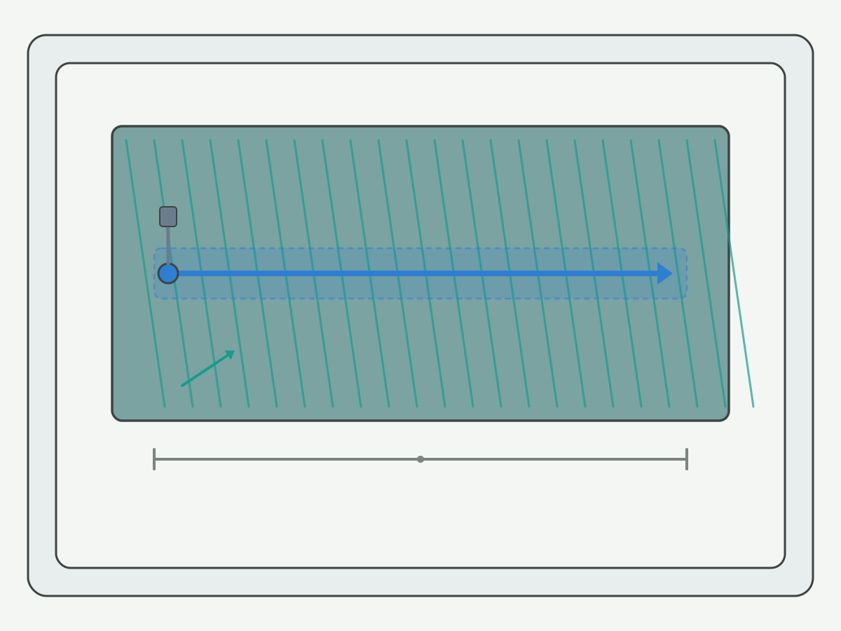
Record the path relative to lay, the instrument evaluation mode, filter and length settings, stylus or optical conditions, and any form-removal steps. On many textured surfaces, measurement across the lay is the usual shop habit, but the final direction follows the drawing, the method, and the function. National measurement institute work on surface texture calibration and uncertainty context is also described on this PTB surface metrology group overview.
Prepare the Surface Without Changing It
Clean and check for residue. Do not polish, wipe-scratch, or otherwise alter the surface before measurement unless the procedure allows it. Confirm instrument status and applicable calibration records. Support the workpiece, watch vibration, and control temperature when the feature and tolerance need it.
Record More Than One Roughness Number
Save the traceable measurement file or profile, positions and directions, parameters and units, settings, repeats, and how outliers were handled. Do not cherry-pick locations or delete awkward traces to force a pass.
Resolve Disagreement Between Two Measurement Results
- Same position and direction?
- Same parameter definition?
- Same filter, length, and evaluation settings?
- Method and probe suitable for that surface?
- Surface state unchanged between readings?
- Need a deeper look at measurement uncertainty and decision rules?
Only after those checks should you treat the gap as a process problem.
What Causes Poor Surface Roughness in Machining?
This section builds a surface-quality check map. It does not rewrite the full symptom triage on the troubleshooting hub. Each row is observation to check direction, not a unique root cause.
| Observation | Check directions | Evidence to keep |
|---|---|---|
| Clear feed marks | Feed, edge geometry, toolpath, and lay direction | Parameters and profile periodicity notes |
| Waviness or regular ripple | Vibration, support, and engagement | Location, assembly, and process record |
| Smearing or material pull | Edge state, adhesion, and cutting conditions | Local tool and workpiece photos |
| Isolated deep scratch | Chips, edge damage, and later handling | Scratch map, chip evidence, operation order |
| Finish worsening over time | Tool use stage and process drift | Measurement trend by sequence |
| Roughness OK but function fails | Parameter coverage, form, lay, and local defects | Full drawing and functional test results |
If the shop problem is sudden breakage, loud chatter, burr growth, or an oversized reading without a finish question, return to the CNC machining troubleshooting hub already linked in the opening instead of stretching this finish guide into full fault triage.
How Can Turning Surface Finish Be Improved?
Turning finish responds to feed, nose geometry, edge condition, and stability together. Change one story at a time and remeasure size and form with the roughness.
Review Feed, Nose Radius and Edge Geometry Together
Judge feed per revolution with nose radius, depth of cut, material, edge geometry, and the stiffness of the tool and workpiece system. Ideal geometric roughness formulas that relate feed and nose radius assume a clean geometric scallop, a suitable nose regime, and stable cutting. They are planning aids only. Do not treat a formula result as a measured Ra, and do not extend a simple nose model to every wiper-style edge without a separate prove-out. Practical turning quality factors (geometry, conditions, and process stability language) are organized in this turning component quality factors overview. Use it as a checklist discipline, not as HENTRY catalog limits.
Check Built-Up Edge, Wear and Chip Contact
Watch whether surface change tracks edge state. Confirm chips are not rubbing the finished surface. Material adhesion or wear can rewrite the actual cutting geometry. Coolant and lubrication must match the material and tool family on your traveler.
Improve Stability Before Chasing a Lower Roughness Number
Check workpiece support and tool stick-out. Separate OD, slender shaft, and ID turning risks. A larger nose radius is not always better. Wiper-style edges are conditional options, not a universal upgrade. Broader surface-finish optimization checklists that separate process factors from wishful feed cuts include this surface finish optimization checklist.
Verify Size and Form After the Change
Remeasure roughness, diameter or size trend, applicable roundness or taper, and how quality moves as the edge wears. When evidence already points to insert-family fit inside HENTRY supply scope, open turning insert selection as a selection entry. HENTRY turning model numbers and promised Ra capability are out of scope on this page until supply evidence is confirmed.
How Can Reaming Finish Be Improved?
Reaming finish starts from the pre-hole, then alignment, tool condition, cutting conditions, and where you measure the bore. Reaming should not be sold as a cure for every pre-hole geometry error.
Start with the Pre-Hole Condition
Record pre-hole size and how it changes with depth, allowance distribution, existing scratches, interrupted zones, entry state, and material condition. For allowance selection detail, use the live PCD reamer allowance and pre-hole size guide instead of repeating a generic allowance table here. Pre-hole quality habits belong on PCD reamer pre-hole quality.
Check Alignment, Runout and Tool Condition
Confirm how the tool relates to the pre-hole, holder seating, measure section and method, and the state of cutting edges and guiding lands. A static runout number is not the same as the cutting result. Deeper PCD reamer control of hole accuracy and surface finish lives on PCD reamers hole accuracy and surface finish.
Review Cutting Conditions and Chip Evacuation
Match conditions to reamer type and material. Cutting feed lower is not a default finish fix. Verify coolant, chip evacuation, and whether chips mark the finished wall. Judge through-holes, blind holes, cross-holes, and interrupted zones separately. Architecture families for reaming tools (structure discovery only) are outlined in this reaming tool architecture overview.
Measure the Bore Surface Where It Matters
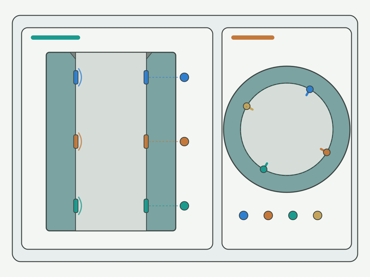
Plan candidate zones near entry, mid-depth, and near the bottom, plus circumferential positions, within probe reach. Note when chamfers, cross-holes, or other interruptions are excluded. These are inspection-planning cues, not a fixed point count for every part. Size faults that are not finish questions may need oversized holes with a new carbide drill when the process is still in drilling.
Confirm Finish Without Sacrificing Bore Quality
Joint-check surface parameters, bore diameter, applicable roundness or cylindricity and position, local scratches, and function. Reaming does not automatically correct position or straightness errors left by the pre-hole. When evidence points to reamer-family fit, open PCD reamers or carbide reamers after pre-hole and allowance notes exist. Series discovery also lives on reamer types and materials.
How Do You Validate a Surface Finish Improvement?
Turn a hopeful feed change into a traceable quality decision. One green reading is not enough.
Keep the Measurement Conditions Comparable
Before/after comparisons need the same instrument class and method, the same parameter and standard settings, the same positions and directions, the same cleaning and process state, and the same data handling, or an explicit note of every difference.
Record the Process Change and Its Side Effects
Write what changed and why, old and new conditions, linked parameters that had to move together, surface size and form results, and tool state by sequence. Prefer controlled changes. When feed and speed must move together, say so on the traveler.
Separate a Successful Trial from Production Capability
One improved reading describes that measurement. A few good parts do not automatically prove long-term process capability. Sampling, capability language, and release follow your approved quality plan. This page does not set a universal trial piece count or a Cpk target.
Define When the Process Must Be Rechecked
- Tool or supply-lot change.
- Regrind, holder change, or stick-out change.
- Material, coolant, or program change.
- Measurement method change.
- Trend drift or functional failure.
Surface Finish Inspection and Trial Record
Use a fillable body checklist. A separate downloadable form is not claimed until a tested file exists. Leave result cells blank on the floor; leave unknown values blank.
| Field | What to capture | Result / entry |
|---|---|---|
| Workpiece and surface | Part number, revision, feature location | |
| Requirement | Parameter, unit, limit, standard and edition | |
| Process | Turning / reaming, material, tool and assembly | |
| Instrument | Device, probe or optics, status record | |
| Settings | Mode, filter, lengths, and other applicable settings | |
| Measure positions | Locations, directions, surface state | |
| Baseline | Readings and original file IDs | |
| Process change | What changed, why, linked conditions | |
| Remeasure | Surface, size, and form results | |
| Decision | Pass / fail / hold, owner, date |
Add rows for extra positions instead of compressing every location into one average.
When Should You Ask for Tooling or Application Support?
Stage the ask so the package matches the open question.
- Requirement or measurement still unclear: send the drawing callout, acceptance language, and the measurement settings you can already name.
- Finish problem with a clear process: send the trial record fields above, plus tool assembly and the last change.
- Reselection or prove-out needed: send drawing, material, quality targets, and the open question after the record is filled.
Primary action: Send Your Drawing and Surface Finish Record. First submission should include material and process, drawing or critical finish and size calls, current tool and main conditions, baseline and remounted readings, and changes already tried. Quantity and purchasing detail can wait until selection or quote. Quotation turnaround after complete drawing information is typically 1 to 2 working days (quotation only, not a delivery promise). Attachment limits follow the live form.
Related Guides and Product Entries
This page owns drawing-to-measurement-to-turning-or-reaming improvement and joint acceptance. Symptom triage stays on the troubleshooting hub already linked above. PCD reamer surface and accuracy deep dives, allowance, pre-hole quality, reamer types, turning insert selection, and oversized-hole diagnosis are linked once each in the body where the task fits. Do not merge those URLs into this page.
For a broader machining handbook overview that can keep short finish notes inside a longer manual, see the live CNC machining handbook. That handbook and this guide interlink; they are not merged and neither should 301 into the other. Product entries for PCD reamers and carbide reamers appear once each above when evidence already points to tool-family fit.
Evidence Notes
Owned on this page. Parameter and unit reading habits, Ra versus Rz boundary without fixed conversion, comparable measurement checklist, turning and reaming improvement order, validation and trial-record fields. Illustrations FIG1–FIG4 are schematics for similar-Ra profiles, roughness/waviness/lay, measure direction, and bore measure zones. They are not customer case photos and carry no life or percentage claims.
Not claimed. Fixed Ra to Rz factors, unverified process-capability guarantee charts, universal trial piece counts, Cpk targets, HENTRY case numbers, tool life multipliers, prices, stock promises, and grinding/honing encyclopedias. SERP volume and keyword difficulty were not verified for this URL (N/A). HENTRY production contour records and rematte product shots remain HOLD until application engineering supplies anonymized assets.
Authority links in the body. Outbound references are specific standards and metrology/education pages used for parameter definitions, specification operators, areal versus profile boundary, measurement method discipline, filtering and evaluation length literacy, turning quality checklists, surface-finish optimization structure, and reaming architecture discovery. Visible anchors stay neutral. Competitor brand names are not used as body marketing labels. None of those links transfers another maker's catalog Ra limits onto HENTRY tools.
Machining Surface Finish FAQ
Does a lower Ra always mean a more accurate part?
No. Surface roughness, size, and form answer different questions on the drawing. A lower Ra reading does not prove diameter, roundness, or position are inside tolerance. Keep finish, size, and form on separate checks, and recheck size and form after any finish change.
Can Ra be converted to Rz with a fixed factor?
No universal fixed factor applies across materials, processes, and filters. Ra and Rz describe different features of the same profile family. Convert units only inside the same parameter, for example micrometres to microinches for Ra alone, and keep the rounding rule with the record.
Why do two labs report different roughness on the same surface?
Different position or direction, different parameter definition, different filter and evaluation settings, different instrument class, or a surface that changed between measurements can all move the number. Resolve disagreement by matching location, parameter, settings, and surface state before you rewrite the process.
What should I check before changing feed to improve turning finish?
Review feed together with nose radius, edge geometry, depth of cut, material behavior, and system stability. Check built-up edge, wear, and chip contact with the finished surface. Improving support often matters before chasing a lower roughness number. After any change, remeasure roughness, size, and applicable form.
Can reaming fix every pre-hole geometry problem while improving finish?
No. Reaming can improve bore surface quality when pre-hole condition, alignment, tool state, and chip evacuation fit the job. It should not be treated as a universal fix for position, straightness, or every form error left by the pre-hole. Record pre-hole size and condition before you change the reamer.
What belongs in a surface-finish trial record?
Capture workpiece and feature identity, required parameter with unit and standard, process and tool assembly, instrument and settings, measure positions and directions, baseline readings with file IDs, the process change and linked conditions, remounted surface size and form results, and the pass fail or hold decision with owner and date.
Should contact and optical roughness readings be treated as interchangeable?
Not by default. Contact stylus and optical methods can disagree when accessibility, reflectivity, surface slope, filtering, or evaluation bandwidth differ. Compare results only when the method, settings, and feature access are recorded, and treat a method change as a new measurement condition.
When must a validated finish process be rechecked?
Recheck after tool or supply-lot change, regrind, holder or stick-out change, material or coolant change, program change, measurement-method change, trend drift, or a functional failure. A successful trial window does not automatically prove long-term process capability.
Send Your Drawing and Surface Finish Record
If measurement alignment and the deep-dive pages still leave an open tooling or prove-out question, send the drawing with the filled surface-finish trial record. Use the RFQ link in the support section above so the package starts from the same minimum fields: material and process, drawing or critical finish and size calls, current tool and conditions, baseline evidence, and changes already tried.