
Chips look short and curled on the tray, yet the flute still packs at depth. Another hole throws a long spiral that looks dramatic but loads the spindle the same as last good piece. Color shifts from silver to straw on stainless after a coolant pause, and someone asks whether blue means the tool is finished.
Drilling chip shape can hint at chip breaking, process stability, and evacuation risk, but a good-looking chip does not prove safe evacuation. Color must be read with material, coolant, surface state, and how the sample was taken; it is not a universal temperature scale. Compare changes under the same material and conditions first, then verify with load, hole quality, and tool inspection.
HENTRY publishes this page as a visual diagnosis guide for metal CNC drilling, with solid carbide drills as the primary scope. Indexable insert drills, when mentioned, are labeled separately because flute volume and chip formation differ. The page stops at recognition and first checks. Packing cleanup trees, wear atlases, breakage analysis, and full feeds validation live on sister pages linked once each.
Read in order when you have chips on the bench: collect a representative sample safely, name the shape family, read color only inside material and coolant context, then connect observations to one checkable variable. Jump to return-path teaching when chips look right but still will not leave a deep or blind hole. Jump to the stop list when load, sound, or discharge changes suddenly.
How to Collect Representative Drilling Chips Safely
A chip photo without process context is decoration. Build a sample you can compare tomorrow under the same material and hole. Safety comes first: stop the spindle and confirm motion has ceased before you reach into the work area.
| Chip Sample Record field | Minimum useful detail | Why it matters |
|---|---|---|
| Stop and collect method | Machine stopped per plant procedure; chips taken with brush, magnet, or scoop, never by hand on a hot or sharp pile | Protects people; avoids mixing samples from a spinning tool |
| Material grade and condition | Exact grade; annealed, tempered, aged, cast, or as noted on the print | Shape and color baselines differ by grade and temper |
| Tool type and diameter | Solid carbide drill diameter; point style; through-coolant yes/no; coating if marked. Label indexable drills separately | Geometry and flute space change chip form |
| Hole: diameter, depth, through/blind | Programmed diameter and depth; through or blind; pilot or cross-hole notes | Sets expected return path and sample stage |
| Speed, feed, peck | Programmed S and F; continuous or peck; any mid-run change | Ties shape change to a controllable lever |
| Coolant route and condition | Flood or through-tool; nominal pressure if known; outlet clear or blocked notes; mix or oil | Color and packing often track delivery more than catalog speed |
| Sample stage | Entry, steady drilling, breakthrough, or labeled mixed if unknown | Prevents judging a whole cycle from one stage |
| Photo setup | Scale in frame; consistent lighting; dry or blot oil glare | Makes same-material comparisons fair |
| Current problem | Noise, torque, finish, size, packing, or no complaint yet | Links chip look to the scrap or alarm you are solving |
Do not scoop from a mixed hopper and claim the sample represents one hole. If you cannot tell which stage produced the chips, mark the card mixed. Bag chips with the card so the next shift does not merge two materials on one tray.
Photograph with a scale and side light when you can. Wipe loose oil without scrubbing away adhesion you need to show. Unknown fields stay blank; a blank is better than a guessed pressure or an invented hole count.
Short Curled Chips: When They Suggest Manageable Chip Formation
Short curled chips often mean the edge is breaking the chip into lengths the flute can carry. On many steels and some aluminum setups they look like compact C-shapes under a loupe. Manageable formation is not the same as proven evacuation.
Shop look: compact curls or C-shapes of similar length from both flutes, little string between curls, and a clean pile at the hole entrance when through-coolant is working. Size and finish may still be good. Treat this as a formation clue, not a green light for deeper holes or higher feed.
What short curls do not prove: that the return path at full depth is clear, that blind-hole bottoms are empty, or that the next material lot will behave the same. A short chip that forms and then wedges in a narrow flute is still a packing risk. Shorter is not always better; over-broken powder in a tough alloy can signal a different problem than a controlled curl in mild steel.
First checks when short curls appear after a change: confirm both flutes produce similar forms, confirm coolant outlets are open, and compare entry versus steady-stage samples. If curls shorten suddenly with rising load, inspect the edge for chipping or built-up edge before you celebrate the new shape.
Long Spiral and Stringy Chips: What to Check First
Long spiral or stringy chips look alarming on the floor. They can wrap the tool, catch on the chuck, or bridge the flute. They are not a one-line diagnosis that feed is too low.
Shop look: continuous or semi-continuous ribbons, corkscrews, or string that bridges flutes. One flute may throw string while the other breaks, which often points to uneven lip load or runout rather than a catalog feed error alone.
Check order for long chips on solid carbide drills:
- Material and condition: gummy grades and soft tempers throw longer chips than the same family name in a harder state.
- Feed per revolution relative to the approved window for that drill and material, without treating long form as automatic proof of low feed.
- Geometry and flute space: web, rake, and flute volume versus hole depth.
- Edge state: dull lips and built-up edge change chip thickness and curl.
- Coolant and evacuation: flow, pressure at the tool, and whether chips leave the entrance or stall mid-flute.
Long chips during entry alone can be normal for some setups; long chips that continue through steady depth and then nest at the mouth need the packing sister page after you finish recognition here. Do not raise feed outside the approved window only to force a shorter chip photo.
Needle-Like, Splintered and Powder-Like Chips
Needle, splinter, and powder forms appear in brittle materials, in interrupted conditions, or when the edge is fracturing the chip into fines. They also appear when a tough material is being cut with an edge that is chipping rather than shearing cleanly. Do not diagnose carbide edge fracture from a chip photo alone.
Shop look: needles or splinters with sharp ends; powder or dust mixed with short fragments; sometimes a spray rather than a curl pile. Cast irons often produce fine chips by material nature. A sudden shift from curls to needles in a previously curling steel or aluminum cut is a different story and needs an edge inspection.
Separate material-typical fines from process alarms. Cast iron and some powdered metals throw fine chips even with a healthy edge. A ductile aluminum that suddenly powders may mean the edge is rubbing, the speed window is wrong, or the sample is mostly breakthrough dust. Record material type on the card before you compare to any reference photo.
First checks: confirm material family, inspect both lips under magnification for micro-chipping, check for vibration or dwell at engagement, and compare entry versus breakthrough samples. Pair chip photos with a tool photo when you suspect edge damage. Wear-location detail belongs on the wear-types page after you finish the chip record here.
Bird Nesting and Chip Packing: Recognizing the Warning Signs
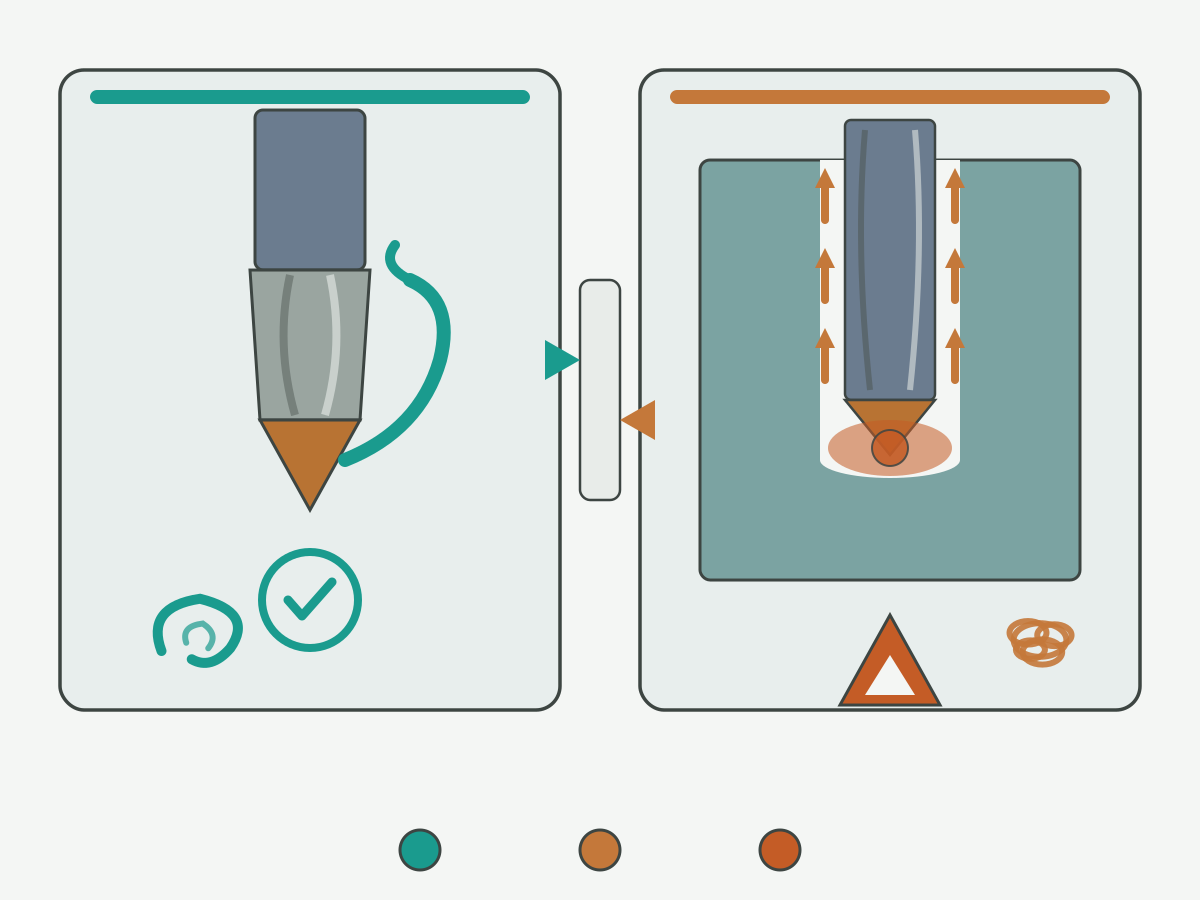
Bird nesting is a tangle of chips around the tool, holder, or hole mouth. Chip packing is compacted chips jammed in the flute or at the hole bottom. Both are evacuation failures. This section only teaches you to recognize them. It does not replace a packing cleanup and process tree.
Shop look: a nest wrapped on the shank or chuck; flutes stuffed with compacted ribbon; chips erupting late or not at all while torque climbs; sudden silence in chip discharge after a previously steady stream. A nest can form even when individual chip pieces look short and curly in a tray sample taken after you cleaned the tool.
Recognition rules: if chips are not leaving the hole at a steady rate, or if you see entanglement at the mouth, treat packing risk as active. Stop and inspect rather than peck harder as a habit. Formation that looked acceptable on a shallow hole does not clear a deep-hole return path.
When recognition is done and you need the shop checklist for causes, cleanup, and process fixes, use the sister page to diagnose and resolve chip packing during drilling. Keep this page focused on what the pile and flute are telling you before you open that tree.
Drilling Chip Colors: Useful Clues, Not a Universal Temperature Scale
Chip color can help when you hold material, coolant, surface state, and sampling method constant. It cannot serve as a universal silver-yellow-blue temperature legend across materials. Aluminum oxide films, stainless heat tint, steel temper colors, and cast-iron gray all mean different things. Flood coolant can wash or stain surfaces that look different under dry cut light.
Use color only after you name the material and how the sample was cooled and stored. A straw tint on one steel grade under flood coolant is not the same clue as a straw tint on stainless after a dry peck. Do not build a cross-material color chart on this page or in the shop binder from this guide.
| Observation | What it can help you judge | What it cannot alone prove |
|---|---|---|
| Sudden color change vs yesterday on the same material, same coolant, same sample stage | Something in heat, delivery, speed, or surface state shifted | Exact edge temperature, tool life left, or that speed must rise or fall by a set amount |
| Color differs between entry chips and steady-depth chips (same material) | Engagement, coolant reach, or packing may differ by stage | That the whole cycle is safe or unsafe |
| Discolored chips with clear coolant starvation signs (dry lips, smoke, blocked outlet) | Prioritize coolant path and outlet inspection | A numeric temperature or a coating failure by photo alone |
| Bright metallic chips with stable load and good finish | Formation may be steady for that material under current coolant | That evacuation at full depth is clear |
| Stained or filmed chips after sitting in coolant or oil | Storage and quench history matter; re-sample fresh if needed | In-cut heat from a tray sample hours later |
| Color compared across two different alloys on one photo board | Almost nothing diagnostic | Any shared temperature or go/no-go rule |
Photograph color under consistent light next to a neutral card when you document a change. Note whether chips were quenched in coolant, air-cooled, or wiped. HENTRY does not publish absolute chip temperatures or a multi-alloy color legend. Keep color as a secondary clue behind shape, load, and tool condition.
How Feed, Speed, Coolant, Geometry and Wear Interact
Chip appearance is the output of several inputs at once. Treat each observed change as a short list of contributors, then pick one first check and the evidence you need. Do not map one shape to one parameter error.
| Observed change | Possible contributors | First check | Evidence needed |
|---|---|---|---|
| Chips lengthen into string on the same material | Feed window; edge dulling; BUE; gummy lot; flute load; coolant starve | Compare both flutes; inspect lips; confirm coolant outlets | Before/after chip photos; lip photos; S/F and coolant notes |
| Chips shorten to powder or needles unexpectedly | Edge micro-chip; vibration; wrong speed window; brittle stock; dwell | Magnify both lips; check stick-out and engagement | Edge photos; sample stage label; load trend |
| Color shifts with stable shape | Coolant mix or flow; surface film; sampling delay; speed change | Coolant delivery and fresh sample under same light | Coolant route notes; paired photos same stage |
| Good curls but rising torque at depth | Return-path restriction; packing; blind bottom fill; blocked outlet | Stop; clear flutes; inspect outlets and depth vs flute volume | Depth, through/blind, pressure/flow notes; packing photos |
| One flute long, one flute short | Runout; uneven lip grind; unequal chip load | Lip height and holder runout | Both-lip photos; runout reading if available |
| Finish worsens while chips look unchanged | Margin rub; BUE shedding; wear at corner; loose holder | Inspect margins and corners; re-check hole trend | Wear photos; size/finish log; link wear ID next |
Feed per revolution influences chip thickness and curl, but only inside the tool and material window you already validated. Cutting speed influences heat and built-up edge risk; it is not a color dial. Coolant delivery means flow and outlet condition, not only a programmed pressure number. Geometry and flute space set how much chip the tool can carry. Edge wear and chipping change formation mid-lot. Runout and weak setups create unequal chips that look like parameter problems until you measure the holder.
When the edge itself is the question, identify wear location on drill wear types after you lock the chip sample record. When breakage risk dominates, move to why solid carbide drills break once chip and load symptoms are written down. For validating speed and feed inside an approved window, use carbide drill speeds and feeds rather than inventing a new recipe from a single chip photo.
Chip Return Paths in Deep and Blind Holes
Chip formation at the cutting edge and chip evacuation out of the hole are two different problems. A curl that looks textbook in a shallow test hole can still fail to travel the flute when depth, blind bottoms, or weak return flow intervene.
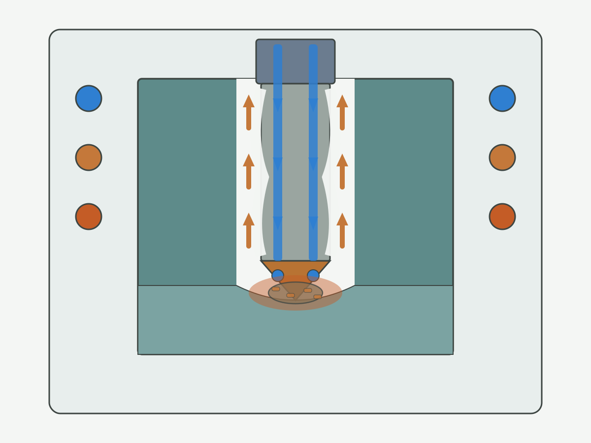
In a typical spiral-flute solid carbide drill with through-tool coolant, fluid leaves the outlets near the point, helps break and flush chips, and must share the flute volume with chips moving toward the hole entrance. Any restriction (narrow flute fill, low real flow, a blocked outlet, or a blind bottom that accumulates chips) can stall return even when the edge still forms acceptable curls.
Teach the path in segments: edge to flute, flute to entrance, entrance clear of nests. Blind holes add a bottom pocket where chips settle when peck or retract does not clear them. Cross-holes and breakthrough change flow suddenly and can throw mixed-stage samples. Pecking is a controlled interrupt, not a universal remedy; pecking into an already packed flute can compact the nest further.
Gun drills and BTA systems use different evacuation architectures. If your process uses them, do not reuse a spiral-flute blind-hole schematic as their return-path map. Label those systems separately and keep this figure scoped to common spiral-flute through-coolant drilling.
Indexable insert drills often present larger chip gullets and different coolant routing than solid carbide bodies. When you compare chip photos across tool constructions, label the construction on the sample card so you do not share one good/bad tag across families.
Change One Variable at a Time and Verify the Result
After you form a hypothesis from chip shape and color clues, prove it with a small, controlled trial. Change one variable inside the approved operating window. Compare equivalent holes and sampling stages. Record chips, load, hole quality, and tool condition before you keep the change.
| Trial record field | What to write |
|---|---|
| Baseline conditions | Material, tool ID, S/F, coolant, depth, through/blind, sample stage |
| Abnormal observation | Shape family, color note, packing sign, load/sound note |
| Hypothesis | One sentence naming the likely contributor |
| Single change | Exactly one lever moved; stay inside approved window |
| Chip photo set | Same stage, scale, lighting as baseline |
| Load or sound change | Qualitative or logged trend; no invented alarm percentages |
| Hole quality | Size, finish, burr, or other print checks you already use |
| Tool condition | Lips, margins, outlets after the trial holes |
| Keep or revert | Decision and next step |
One-variable trials fit stable diagnosis. Clear fault signals (sudden torque spike, no chip discharge, suspected broken edge) require stop and inspect first, not a parameter experiment. Do not change feed, speed, and coolant together and then claim the chip photo proved a single cause.
Write the trial on the same card family as the chip sample record so the next shift can repeat the comparison. If the single change improves chips but worsens finish, revert and open a new hypothesis rather than stacking a second change on top. Keep the approved window visible on the traveler so operators do not invent a third speed mid-lot to chase a photo.
When to Stop Drilling and Inspect the Tool
Stop rules protect the part and the spindle. Use plant and process limits you already validated. HENTRY does not publish a universal load-alarm percentage for every machine.
| Stop trigger | What to do before restart |
|---|---|
| Sudden change in load, sound, or vibration | Stop; clear chips; inspect drill, flutes, holder, and workpiece feature |
| Interrupted chip discharge or visible entanglement | Clear nests; inspect outlets and flute fill; do not force peck through a pack |
| Suspected coolant loss or tool damage | Confirm flow at the tool; inspect lips and margins; quarantine damaged tools |
| Abrupt hole-quality escape (size, finish, burr) | Correlate with chip sample and edge photos; fix cause before more holes |
| Unknown chip origin after a crash or tool change mix-up | Relabel samples; do not diagnose from a mixed hopper scoop |
Before restart, confirm the drill is undamaged or correctly replaced, flutes and outlets are clear, holder torque and stick-out match the process sheet, coolant is reaching the tool, and the next sample stage is defined. Write the restart conditions on the same card as the chip record.
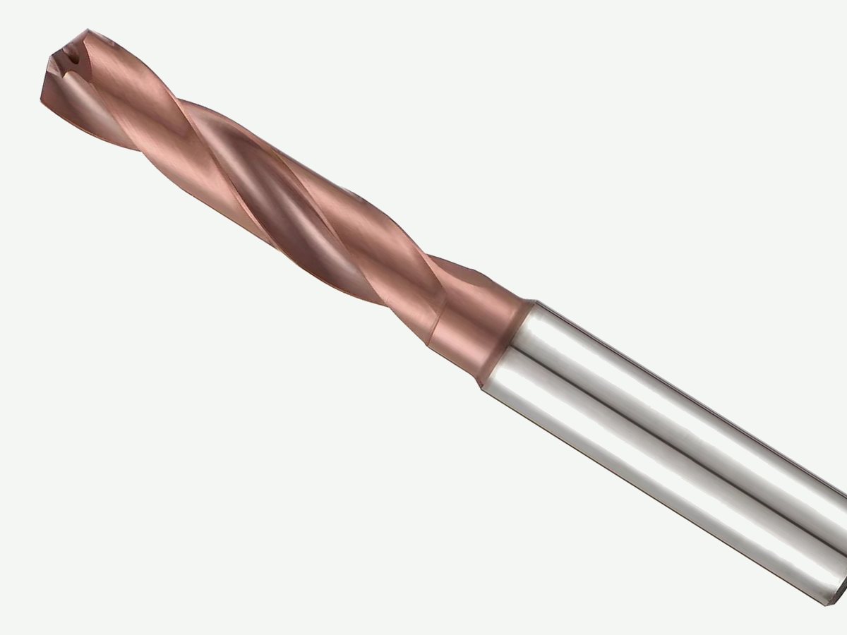
When you need an engineering review, send chip photos, tool photos, and the filled condition fields. Do not send only a note that asks what blue chips mean. Geometry and coating choices for a replacement solid carbide drill need that full package, not a color word alone.
Drilling Chip Shapes and Colors FAQ
What can drilling chip shape tell you about the process?
Chip shape can hint at chip breaking, process stability, and evacuation risk. Short curls often suggest manageable formation; long string raises wrapping and packing concern; needles or powder need a material and edge context. Shape alone cannot prove safe evacuation at full depth or that parameters are correct.
Why is a good-looking chip not enough to trust evacuation?
Formation at the edge and travel out of the hole are different problems. Curls that look fine in a shallow sample can still stall in a deep or blind hole when flute volume, coolant return, or a blind bottom restricts flow. Confirm discharge at depth and inspect for packing signs.
How should I read drilling chip color?
Read color only with material, coolant, surface state, and sampling method held in view. A change under the same material and conditions can flag a heat or delivery shift. Color cannot serve as a universal temperature scale across alloys, and tray samples that sat in coolant may not show in-cut appearance.
What should I record when I collect drilling chips?
Record stop method, material grade and condition, tool type and diameter, hole depth and through or blind, speed and feed, coolant route, sample stage, photo setup, and the current problem. Mark mixed samples when the stage is unknown. Include a scale in at least one photo.
When do bird nests or packed flutes mean I should open the packing checklist?
When you see entanglement at the mouth, compacted chips in the flutes, interrupted discharge, or rising torque with poor chip exit, recognition is done and you need the packing diagnosis and cleanup tree. Finish the sample card here, then follow the packing checklist for resolution steps.
How do I run a one-variable chip trial safely?
Lock a baseline, state one hypothesis, change one lever inside the approved window, and compare equivalent holes and sample stages. Record chip photos, load or sound, hole quality, and tool condition, then keep or revert. Stop and inspect first when fault signals appear instead of experimenting through an alarm.
When should I stop drilling because of chip symptoms?
Stop for sudden load, sound, or vibration changes, interrupted discharge or visible nests, suspected coolant loss or tool damage, and abrupt hole-quality escapes. Clear and inspect the drill, flutes, holder, and workpiece before restart. Do not use a universal load percentage from this page.
Can I use the same good or bad chip labels for solid carbide and indexable drills?
No. Solid carbide spiral drills and indexable insert drills differ in flute volume, insert geometry, and often coolant routing. Label the tool construction on every sample card. Compare chips within the same construction and material before you borrow a shape tag across families.
Send Chip Photos and Drilling Conditions for Review
Attach chip photos with scale, tool photos, and the sample record fields. HENTRY reviews solid carbide drill geometry and process fit against the formation and evacuation clues you documented, then quotes to the drawing.