
Search results for ramping, helical ramp, and centre cutting often mix CAM path tips, catalog center-cutting notes, and feed tables on one screen. Process engineers and CNC programmers then open several tabs and still lack a single place to separate linear from helical entry, confirm whether the end mill is center-cutting, balance ramp angle against axial load, and check chip escape, collision, and aperture limits before an RFQ.
HENTRY publishes this guide as a milling entry and path-selection hub. You walk linear versus helical paths, then a center-cutting yes-or-no check, then ramp-angle and axial-load tendency, then chip, collision, and aperture conditions, then a select-and-verify path that ends at a live end-mill product page or a tooling review. The page does not host a full milling-tools encyclopedia, a carbide or high-feed buy table, or an invented HENTRY-measured ramp-angle or feed guarantee posed as shop data. Buy-select geometry belongs on the carbide end mills and high-feed end mill product pages; here you finish path and capability checks before you request a review.
Linear vs helical jumps to path comparison. Center-cutting opens the capability checklist. Select & verify opens the selection boundary and RFQ fields.
Ramping and helical entry let an end mill reach depth without a full plunge. Linear ramps move on a slanted XY path; helical ramps spiral while cutting. Confirm the tool is center-cutting before any plunge-like move, then set ramp angle against axial load, chip escape, and collision or aperture limits. Match path and checks first, then open carbide or high-feed end-mill product pages - or send an RFQ to HENTRY with material, cavity, and tool constraints.
Linear vs Helical Entry Paths
Use the path checklist below as a shop-dependent routing aid, not as a guarantee that one path type fits every cavity, slot, or aperture. Read material, machine rigidity, stick-out, and whether a pre-drill already exists before you lock a strategy. Confirm open cells with engineering when the print, cavity, or tool geometry is still unclear.
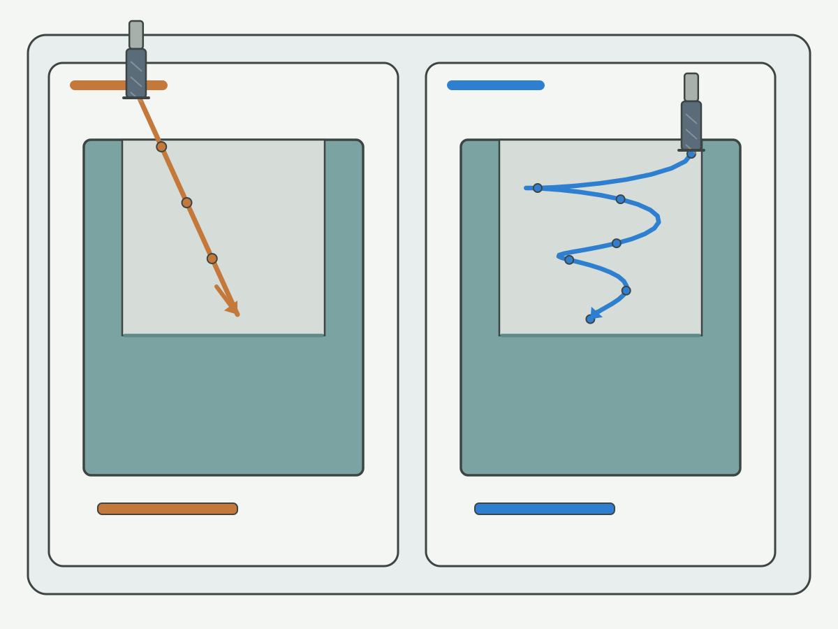
| Path type | What the tool mainly does | When shops often use it | Common mix-up | Leave blank if unknown |
|---|---|---|---|---|
| Linear ramp | Slanted XY feed while Z descends on a straight-slant path | Open slots, simple pockets, entries with clear side clearance | Treating any slant as a full-load plunge | Yes; confirm clearance and chip exit |
| Helical ramp (helical entry) | Circular or spiral XY path while Z descends | Closed pockets, hole enlargement, entries that need a spiral diameter | Calling every ramp "helical" even when the path is a straight slant | Yes; confirm helix diameter vs aperture |
| Full plunge (reference only) | Near-vertical Z entry with little or no XY travel | Only when the tool is rated for center engagement and the process allows it | Using a non-center-cutting tool as if it could plunge | Yes; usually not the default on this hub |
A linear ramp advances in X or Y (or both) while Z drops on a continuous slant. The tool cuts on the periphery and, depending on geometry, on the end as depth increases. A helical ramp (also searched as helical entry or helical ramp) walks a circular or spiral path in XY while Z drops, so the engagement is shared around the orbit rather than concentrated on one straight slant face. Both strategies exist to reach depth without treating the move as a full, unsupported plunge.
Shops often mix the labels. "Ramping" in CAM may mean any non-plunge entry. "Helical" may be used loosely for any curved or slanted approach. On this hub, linear means a straight-slant XY+Z path; helical means a spiral or circular XY path with Z descent. Use the figure trajectories as a memory aid, not as a programmed toolpath file.
When a pre-drilled hole already exists, either path may enlarge or blend into that aperture - but the aperture diameter, remaining stock, and collision envelope still decide whether a helix fits. When no pre-drill exists, closed pockets often favor helical entry because the orbit can stay inside the finished wall; open slots or wide channels may favor a linear ramp if chip exit is clear. Neither sentence is a universal ranking. Material, flute count, and holder clearance still override a default preference.
Keep full milling-process encyclopedias off this page. A broader cutter overview lives on the live milling tools guide when you need series context after the entry decision. Here the open question is which entry path matches the cavity and the tool capability you already have - or the capability you still need to confirm.
Center-Cutting Capability
Center-cutting (US spelling on this site; SERP may also show centre cutting) means the end geometry can cut at or through the tool centerline. Non-center-cutting end mills leave a dead zone at the center and are not rated for a full vertical plunge into solid stock. Confusing those two geometries is a common cause of tip chipping on the first entry move.
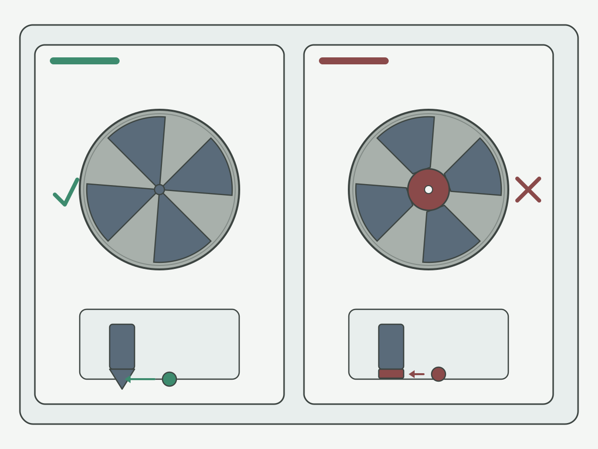
| Check | Yes means | No / unknown means | What to do next |
|---|---|---|---|
| End cutting reaches center | Geometry can engage on or near centerline per maker data | Dead zone at center; no full plunge into solid | Prefer ramp or helical entry; do not invent plunge capability |
| Maker states center-cutting | Catalog or drawing explicitly allows center engagement | Silent catalog line or "peripheral only" note | Treat as non-center-cutting until confirmed |
| Near-vertical entry allowed | Process sheet allows a steep approach with that tool | Only shallow ramps or helical orbits approved | Keep angle and path inside the approved envelope |
| Existing hole or aperture | Entry can start from clearance already in the part | Solid face with no starter | Path and center-cutting checks both matter more |
Read the maker declaration first. If the catalog or drawing does not say center-cutting, do not assume the tool can plunge. Many square and roughing end mills are designed for peripheral milling and for ramped or helical entry only. Using them as if they were drill-style plungers loads the center dead zone and the weakest part of the tip.
A yes on center-cutting still does not unlock an unlimited plunge. Machine rigidity, stick-out, material, and coolant still bound how steep an approach can be. A no on center-cutting does not ban ramping: shallow linear or helical paths are often the intended entry for those tools. The checklist answers capability; it does not replace a process trial or a manufacturer speed-and-feed note.
Do not rewrite non-center-cutting tools as plunge-capable in traveler notes. If purchasing only receives the words "end mill" with no center-cutting flag, send the check back before the first solid entry is programmed. The figure shows a geometric yes-versus-no contrast; it is not a photo of a customer failure and it does not display unverified angles or feeds.
Ramp Angle & Axial Load
Ramp angle describes how steeply Z drops relative to XY travel on a linear or helical entry. As the angle increases, axial and end-cutting load tendency rises because more of the descent is packed into less XY distance. As the angle decreases, the path lengthens, cycle time can grow, and chip volume per unit path may change. Those are tendency statements, not locked HENTRY shop guarantees.
| Tendency | What usually rises | What usually trades off | Boundary note |
|---|---|---|---|
| Steeper ramp angle | Axial / end-load tendency | Shorter XY path; less time in entry | Shop- and tool-dependent; confirm maker limits |
| Shallower ramp angle | Path length and entry time tendency | Lower axial spike tendency on many setups | Still check chip packing and wall clearance |
| Helical orbit diameter | Side engagement pattern around the circle | Must fit aperture / pocket walls | Collision and aperture checks in next section |
Any example degree or feed value you copy from a catalog is manufacturer / shop-trial dependent - not an HENTRY-measured guarantee. Do not treat a single competitor blog number as a universal plant standard. Confirm open cells with engineering when stick-out, material, or holder length differs from the catalog example.
Machine rigidity and tool stick-out amplify axial spikes. A long projection in a soft setup can make a moderate catalog angle feel aggressive. Material and coating change how the end responds to the first engagement. This page intentionally does not publish a fake universal ramp-angle chart. Inventing a complete degree matrix without a named maker source would pose unverified values as HENTRY process data.
When a maker publishes a maximum ramp angle or a helical pitch note for a specific series, copy that series name onto the traveler and keep the number tied to that source. If two makers disagree, stop and confirm rather than averaging. High-feed geometries may prefer different entry envelopes than general-purpose carbide end mills; buy pages carry series detail after you finish the path and load checks here.
Chip Escape, Collision & Aperture Conditions
Entry fails in shops for reasons that are not only about angle. Chips must leave the cut. The holder and workpiece must not collide on the orbit. The aperture or pocket opening must accept the programmed helix diameter or slant clearance. Blind cavities, deep pockets, narrow slots, and hole-enlargement jobs each add a different constraint.
| Condition | What to lock | Risk if ignored | Signal to stop and recheck |
|---|---|---|---|
| Chip escape | Flute space, coolant/air, exit path out of the cavity | Recut chips, heat at tip, poor finish at entry | Unusual noise, burnt chips, sudden load rise |
| Collision envelope | Holder diameter, stick-out, wall and floor clearances | Holder rub, broken shank, scrapped wall | Witness marks on holder or unexpected wall contact |
| Aperture / helix fit | Programmed orbit diameter vs existing hole or pocket | Helix that cannot fit; overcut of finished wall | CAM warning, gouge on first try, incomplete circle |
| Blind vs open exit | Whether chips can leave downward or only upward | Packed floor, tip overload on final depth | Rising Z load near final depth without clear chips |
Blind cavities and deep pockets need an exit plan for chips before the tool reaches final depth. Narrow slots may accept a linear ramp more easily than a wide helix. Hole enlargement needs the orbit to stay inside the stock you still intend to remove, without clipping a finished bore you already cut. Those are process boundaries, not a second encyclopedia on blind versus through holes - keep deep hole-type detail on dedicated drilling resources when those pages are live.
Abnormal signals - unusual noise, vibration, or tip chipping at first engagement - are stop-and-recheck cues. They are not proof of a life-percent claim and they are not a substitute for a documented trial. Log the path type, the approximate angle or pitch from the maker note you used, the stick-out, and the material, then adjust one variable at a time.
Do not paste a competitor feed table into the traveler as if it were an HENTRY guarantee. Do not imply that helical entry is always safer or always faster. Helical entry helps when the orbit fits and chip flow works; it fails when the aperture is too small or the holder collides on the spiral.
Select & Verify Steps
Close the entry decision in order: material and cavity type, path type (linear or helical), center-cutting yes or no, ramp-angle and axial-load boundary from the maker note, chip / collision / aperture checks, then a controlled trial. Only after those fields are named do you open a product page or send an RFQ.
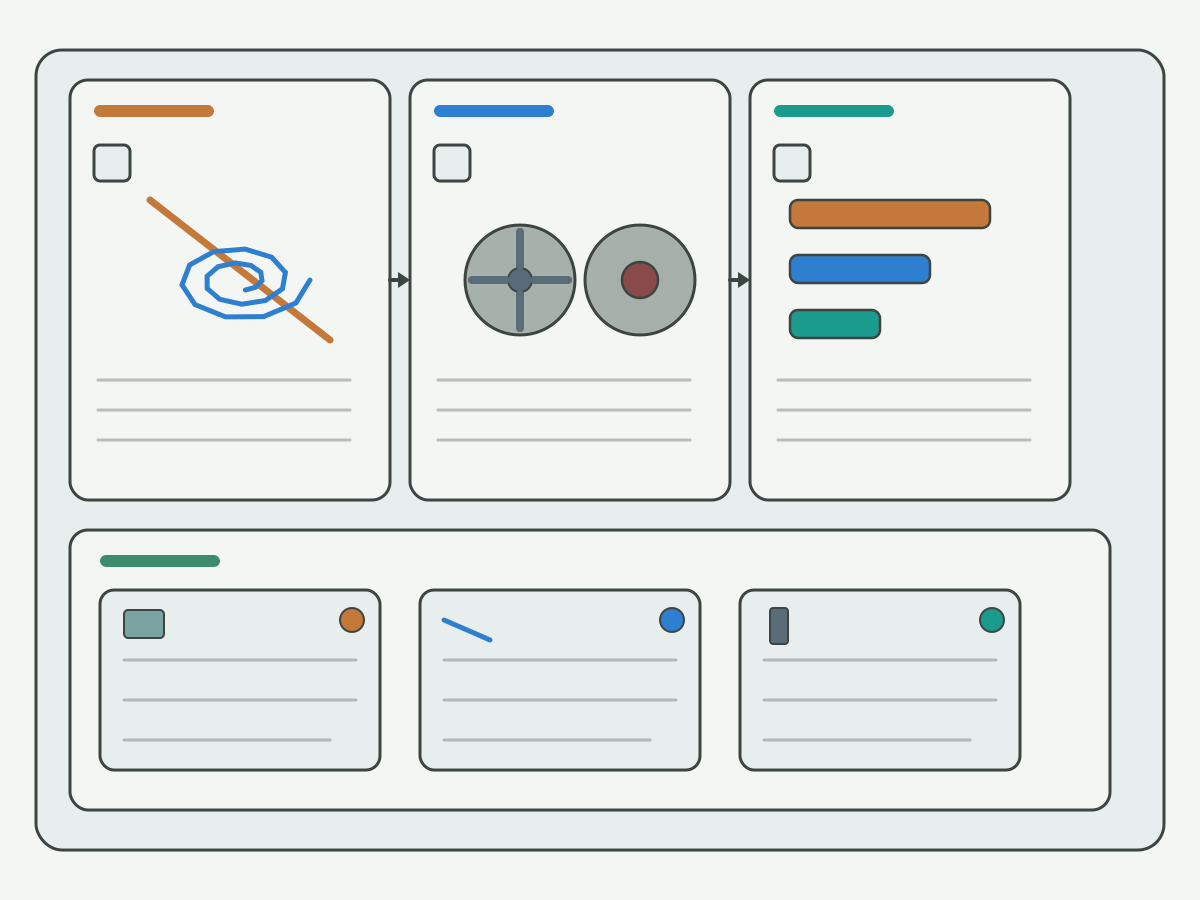
| Step | Lock this field | Pass cue | If still open |
|---|---|---|---|
| 1. Job context | Material, cavity/slot/hole enlargement, machine and stick-out | Traveler names all four | Stop; incomplete RFQ later |
| 2. Path type | Linear ramp vs helical entry | One path chosen with clearance note | Revisit FIG1 comparison |
| 3. Center-cutting | Yes / no / unknown per maker | Flag matches catalog or drawing | Do not plunge; confirm maker |
| 4. Angle / load boundary | Maker or shop-trial limit tied to series name | Source label written beside the number | No orphan degree without source |
| 5. Chip / collision / aperture | Exit path, holder envelope, orbit fit | No unresolved CAM or setup flag | Resize helix or change path |
| 6. Trial then buy or RFQ | Short verification cut or engineering review | Entry stable enough to release | Open product page or RFQ with notes |
When the open question is which solid carbide end-mill series fits after the entry checks, open the live carbide end mills product page once. When the open question is high-feed series selection for shallow, high-feed-style work after the same checks, open the live high-feed end mill product page once. Neither link replaces the path and center-cutting work on this hub, and this hub does not copy those buy tables.
If the traveler still lacks material, cavity type, path choice, center-cutting flag, or aperture notes, send those fields back before purchasing quotes a blank "end mill" line. Custom geometry, special neck lengths, or process review belong on the RFQ after the checklist above is filled as far as the print allows.
Entry Hub vs Product & Related Pages
Keep roles separate so searchers and internal editors do not merge buy pages into this knowledge hub or rebuild the same entry topic on a second thin URL.
| Resource | What it covers | Next step |
|---|---|---|
| This hub (/resources/ramping-helical-entry-end-mills) | Linear vs helical paths, center-cutting check, ramp angle vs axial load tendency, chip/collision/aperture, select and verify | Finish checks, then product or RFQ |
| Carbide end mills (product) | Buy / select solid carbide end-mill series | Open after entry fields are named |
| High-feed end mill (product) | Buy / select high-feed end-mill series | Open when high-feed is the candidate family |
| Milling tools guide (knowledge) | Broader milling cutter overview | Use for series context, not to redo entry checks |
| Shell mill (product) | Shell-mill buy path | Only when shell milling is the actual job |
| Drill bit size chart (knowledge) | General drill size systems and conversion | Optional after milling entry is locked |
| Blind vs through hole (knowledge) | Hole-type and depth routing for drilling | Use when aperture notes need hole-type language |
| Center drill size chart (knowledge) | Center-drill numbering and main dimensions | Use when a center-hole size token is next |
A wider cutter overview lives on the live milling tools guide when you need orientation after the entry decision. Shell-mill purchase detail stays on the shell mill product page when that is the real next buy - not as a substitute for end-mill ramping checks. General drill size, blind-versus-through, and center-drill chart pages are live support links in Related Live Links below - keep their depth on those hubs, not on this entry page. Indexable drills remain unpublished and stay soft-note only.
Related Live Links (Hard Links Only)
| Resource | What it covers | Next step |
|---|---|---|
| Carbide end mills | Solid carbide end-mill product selection | Buy / select after entry checks |
| High-feed end mill | High-feed end-mill product selection | Buy / select when high-feed fits |
| Milling tools guide | Milling cutter overview knowledge | Context after path decision |
| Shell mill | Shell-mill product selection | Only when shell milling is required |
| Drill bit size chart | General drill size systems and conversion | Optional after milling entry is locked |
| Blind hole vs through hole | Hole-type and depth routing for drilling | When aperture notes need hole-type language |
| Center drill size chart | Center-drill numbering and main dimensions | When a center-hole size token is next |
| Custom cutting tool RFQ | Engineering review for open process or geometry fields | Send material, path, and constraints |
Carbide end mills and high-feed end mill links appear once each in the Select & verify section above. The milling tools guide link appears once in the hub-versus-product section. The shell mill link and the three live drill-support Knowledge links appear once each in this table. The RFQ button appears once at the end. Indexable drills stay soft-note only while that product path remains unpublished.
Evidence Notes & FAQ
Evidence on this page is structural: path comparison, center-cutting checklist, ramp-angle versus axial-load tendency, chip/collision/aperture conditions, and select-and-verify steps toward an RFQ. Any degree or feed example must stay tied to a manufacturer or shop-trial source. No customer case study is invented here. No life percentage, price, or stock claim appears.
What is ramping with an end mill?
Ramping is an entry move where the end mill reaches depth while also traveling in XY, instead of a full vertical plunge into solid stock. Linear ramps use a straight slant; helical ramps spiral while descending. Confirm center-cutting capability before any plunge-like move, then balance angle, chip escape, and collision limits for your machine and tool.
Linear ramp vs helical ramp - what is the difference?
A linear ramp follows a straight-slant XY path while Z drops. A helical ramp follows a circular or spiral XY path while Z drops. Closed pockets and hole enlargement often use helical orbits when the diameter fits; open slots may use linear ramps when side clearance is clear. Neither path is universally better; cavity, aperture, and tool capability decide.
Do I need a center-cutting end mill to ramp?
Not always. Many non-center-cutting end mills are intended to enter on a ramp or helix rather than a full plunge. You do need a center-cutting rating (or another approved method) before treating the move as a near-vertical plunge into solid. If the catalog is silent, treat the tool as non-center-cutting until engineering confirms.
How does ramp angle affect axial load?
Steeper ramp angles tend to raise axial and end-cutting load because more descent is packed into less XY travel. Shallower angles tend to lengthen the path and can ease that spike on many setups. Exact limits are manufacturer and shop-trial dependent. Do not treat a single blog degree as an HENTRY guarantee for every material and stick-out.
What chip, collision, or hole limits matter?
Chips need an exit path. The holder needs clearance from walls and floors on the programmed orbit. The aperture or pocket must accept the helix diameter or slant clearance. Blind cavities, deep pockets, narrow slots, and hole enlargement each add constraints. Stop and recheck if noise, vibration, or tip damage appears at first engagement.
How do I select and verify an entry strategy?
Name material and cavity, choose linear or helical, confirm center-cutting yes or no, attach a maker or shop-trial angle boundary, check chip/collision/aperture, then run a short verification cut. After those fields are closed, open the matching end-mill product page or send an RFQ with the same notes.
When is helical entry better than a linear ramp?
Helical entry often helps in closed pockets or when you need to share engagement around an orbit that fits inside the walls. Linear ramps often help in open slots or when a simple slant clears chips sideways. These are scenario tendencies, not a universal ranking. If the helix does not fit the aperture, switch path rather than forcing the orbit.
Where do carbide vs high-feed end mills fit?
After path and capability checks, general solid carbide end-mill selection belongs on the carbide end mills product page. High-feed series selection belongs on the high-feed end mill product page. This hub does not copy those buy tables. Use the RFQ when geometry, neck length, or process limits still need an engineering review.
Request Custom Cutting Tool Support
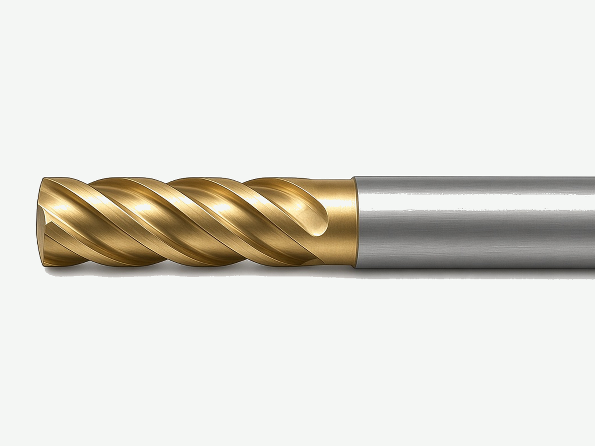
When path type, center-cutting capability, ramp-angle boundary, or chip and collision notes are still open, send the drawing and process notes through a custom review. HENTRY can help close entry and tooling fields before you lock a series.