
Search results for what is a blind hole, blind holes, define blind hole, and blind hole definition often mix textbook definitions with tool catalogs on one screen. Process engineers then open several tabs and still lack a single place to name hole type, bottom geometry, effective depth, chip and coolant paths, and the drill, ream, or tap notes that belong on the drawing before an RFQ.
HENTRY publishes this guide as a hole-type and process hub for CNC machining. You walk blind versus through definitions, then hole-bottom geometry and effective-depth checks, then chip, coolant, and exit behavior, then how drill, ream, and tap differ by hole type, then a drawing information checklist that feeds product pages and a tooling review. The page does not host a full deep-hole encyclopedia, a size-chart dump, a materials comparison, or invented depth guarantees in millimeters. Product families and buy-select geometry belong on the flat-bottom and solid carbide drill pages; here you finish hole-type and depth checks before you request a tooling review.
Definitions jumps to blind versus through. Bottom & effective depth opens the geometry and depth checklist. Drawing checklist opens the RFQ field list.
A blind hole stops inside the part; a through hole exits the far side. That single geometry choice changes bottom shape, effective depth callouts, chip and coolant paths, and how you drill, ream, or tap. Flat-bottom and conventional point drills serve different bottoms; exit burr and breakthrough risk apply mainly to through holes. Capture hole type, depth datum, bottom form, and finish notes on the drawing before you open product pages or request a tooling review from HENTRY.
Blind Hole vs Through Hole Definitions
Use the definitions below as a shop-dependent routing aid, not as a guarantee that every traveler uses the same words. Name hole type on the drawing first, then talk tools. Confirm open cells with application engineering when the print, material, or finishing step is still unclear.
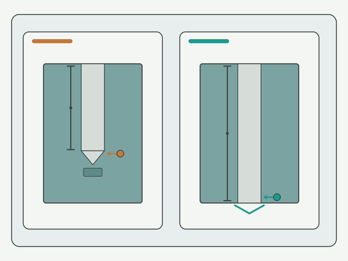
| Hole type | What it means | Exit on far side | Common mix-up | Leave blank if unknown |
|---|---|---|---|---|
| Blind hole | Hole stops inside the workpiece; no through exit | No | Treating drilled depth as usable effective depth | Yes; confirm depth datum |
| Through hole | Hole exits the far face of the workpiece | Yes | Ignoring exit burr and breakthrough load | Yes; confirm exit-face notes |
A blind hole stops inside the part. There is no open exit on the far side, so chips and coolant must leave through the entry, flute, or side path the process provides. A through hole exits the far side. Chips and coolant can leave through that exit, and breakthrough and exit-face quality become part of the traveler.
A frequent traveler error is to treat effective depth as the same number as drilled depth, or to assume a pointed drill leaves a flat usable bottom. Another error is to omit hole type on the RFQ and then debate tools after the quote leaves. Lock hole type first, then bottom form, then depth datum, then finish notes. If purchasing only receives a bare diameter with no hole type, send the type back before the order lands on the wrong process path.
Shop-dependent drawings still need application engineering confirm when the print mixes depth callouts, when a ream or tap follows, or when the exit face is a sealing or mating surface. Keep those notes beside the checklist rather than treating one catalog photo as a locked process sheet.
Hole Bottom Geometry & Effective Depth
Bottom geometry and depth callouts decide whether a conventional point is enough or whether a flat bottom is required. Use the checklist below before you treat a single depth number as both drill depth and usable length.
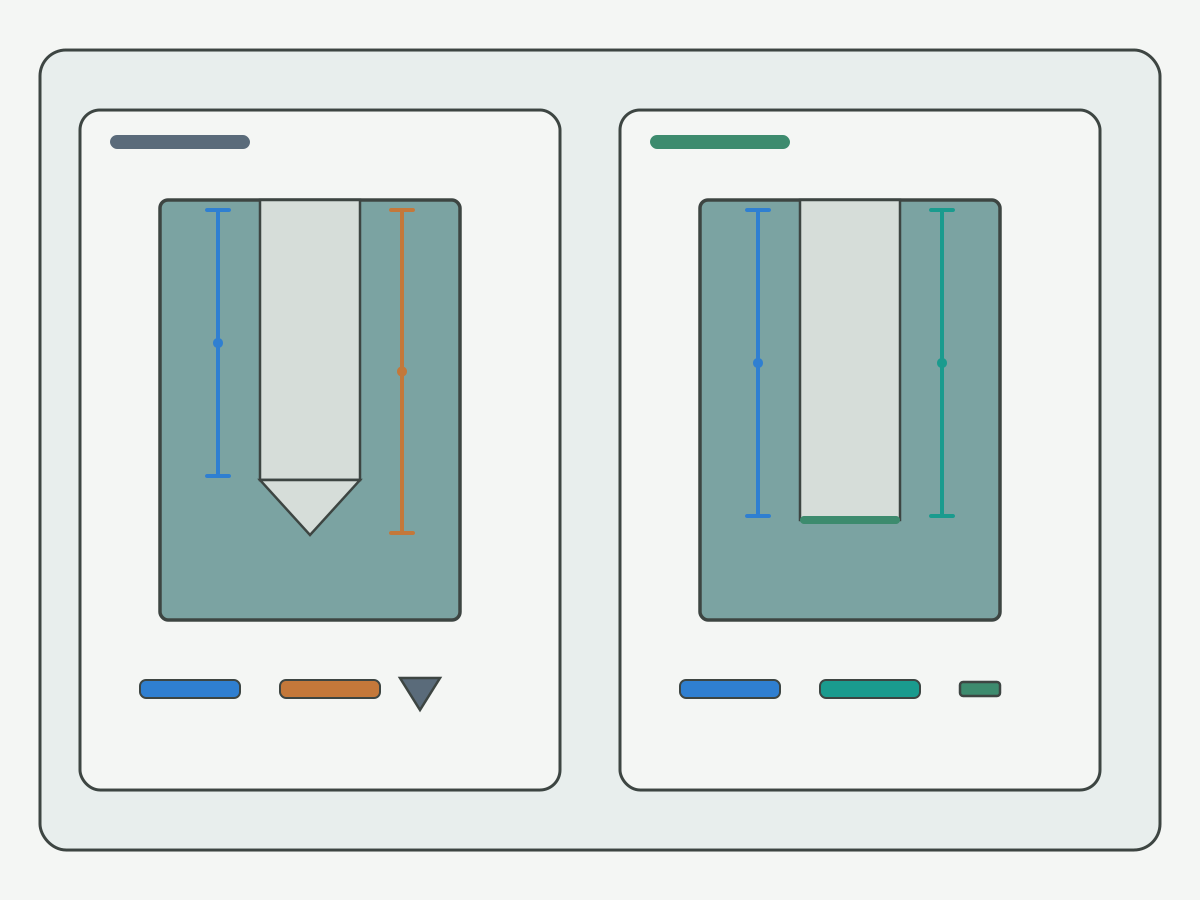
| Checklist item | What to write | When a point tip may be enough | When flat bottom enters the review |
|---|---|---|---|
| Bottom form | Point, flat, or special (print language) | Print accepts a conical tip residue | Print calls for a flat usable floor |
| Effective depth | Usable length from the named datum | Clearance or non-critical depth band | Seal, plug, or mating length is critical |
| Drilled depth | Program or tool depth including tip allowance | Tip allowance already proven on the job | Tip allowance would steal required usable length |
| Thread usable length | Full-thread length if a tap follows | Through tap with clear exit | Blind tap needs unused tip and chip room |
| Datum clarity | From which face or feature depth is measured | Single clear datum on the print | Mixed datums or stacked stock |
Effective depth is the usable length the design needs from the named datum. Drilled depth is often longer because a conventional point leaves a cone that does not count as flat usable floor, and because tapping or plugging may need extra chip or tip room. Thread usable length is a separate callout when a tap follows. Do not invent a fixed millimeter guarantee that converts one number into the others on this page; write the print values you have, or leave the cell blank for engineering confirm.
A flat-bottom drill enters the review when the print needs a flat usable floor, when tip residue would steal required effective depth, or when a later plug or seal sits on that floor. A conventional point often remains enough when the print accepts a conical tip residue and the usable band sits above it. That is a drawing decision, not an absolute rule that every blind hole must use a flat-bottom tool. When flat-bottom geometry is the next product question, open the live flat-bottom carbide drill page for buy-select detail after the depth checklist is named.
Keep depth numbers shop-dependent. Different plants round tip allowance differently, and material push-out or spring-back can move the measured floor. Confirm open depth cells with application engineering before you lock a process sheet or a stocked length.
Chip Evacuation, Coolant & Exit Behavior
Blind and through holes share diameter talk but not chip and coolant paths. Name the path before you chase a single feed or peck recipe.
| Behavior | Blind hole | Through hole | Traveler note |
|---|---|---|---|
| Chip path | Out the entry, flute, or side path only | Can leave through the far exit as well | Write how chips leave; do not assume an exit exists |
| Coolant reach | Harder to flood the floor; packed chips block flow | Exit can relieve pressure and carry chips | Note flood, mist, or through-coolant preference |
| Exit / breakthrough | No far-side breakthrough event | Breakthrough load and exit burr matter | Add exit-face quality notes on through holes |
| Peck / dwell | Often used to clear packed chips | May still help in deep or gummy cuts | Keep peck detail on its own process page |
In a blind hole, chips stack toward the floor if flute evacuation or peck clearing is weak. Coolant may never wet the tip if chips pack. In a through hole, the far exit can help chips leave, but breakthrough can spike load and leave burr or breakout on the exit face. Those are process notes, not a ranking that one hole type is always easier.
Chip color and shape clues continue on the live drilling chip shapes and colors guide. Keep that page for chip diagnosis; keep this page on hole-type routing. When packed chips in a blind hole push you toward peck cycles, open the live peck drilling when required guide instead of copying a full peck encyclopedia here. Through-coolant and deep-hole product choices sit after hole type and depth are named; link them once in related live links rather than expanding a deep-hole OWN dump on this hub.
Do not invent a life percentage or a fixed depth-to-diameter guarantee for either hole type. Write the chip path, coolant style, and exit-face notes you actually know, and leave unknown cells blank for application engineering.
How Drill, Ream & Tap Differ by Hole Type
Drill, ream, and tap all inherit the blind-versus-through choice. Keep each step’s depth and exit notes on the traveler instead of assuming one program covers every hole type.
| Operation | Blind-hole focus | Through-hole focus | What this hub does not own |
|---|---|---|---|
| Drill | Bottom form, tip allowance, chip packing | Breakthrough load, exit burr, exit support | Full product SKU tables |
| Ream | Ream depth vs usable floor; chip room at the bottom | Through ream and exit-edge quality | Reamer type / material encyclopedia |
| Tap | Tap-drill depth, unused tip, chip evacuation before the floor | Through tap and exit chips | Full tap-drill size chart |
Drilling a blind hole needs a clear story for tip allowance and chip clearing at the floor. Drilling a through hole needs a clear story for breakthrough and the exit face. Reaming a blind hole is not the same traveler as reaming through: usable ream depth and bottom clearance differ, so keep reamer selection depth on dedicated reamer resources rather than expanding a reamer hub here. Tapping a blind hole needs unused depth below the full thread and a plan for chips that cannot exit the far side; a through tap can push chips out the exit. Full tap-drill tables belong on a dedicated tap-drill size chart resource when that page is live; until then, put thread, pitch, material, and tap-drill preference on the RFQ instead of inventing a tap table on this hole-type hub.
Size tokens and inch-metric conversion sit outside this page. When you need numbering systems and conversion examples after hole type is locked, use the drill bit size chart resource when that page is live; until then, write the preferred size system on the RFQ. Substrate choice among HSS, cobalt, and carbide continues on the materials guide linked in the process-versus-product section below. Keep those size and materials OWN blocks off this hole-type hub.
Drawing Information Checklist Before RFQ
Most hole-type RFQ failures are missing fields, not missing catalog photos. Close the checklist before you open a product family.
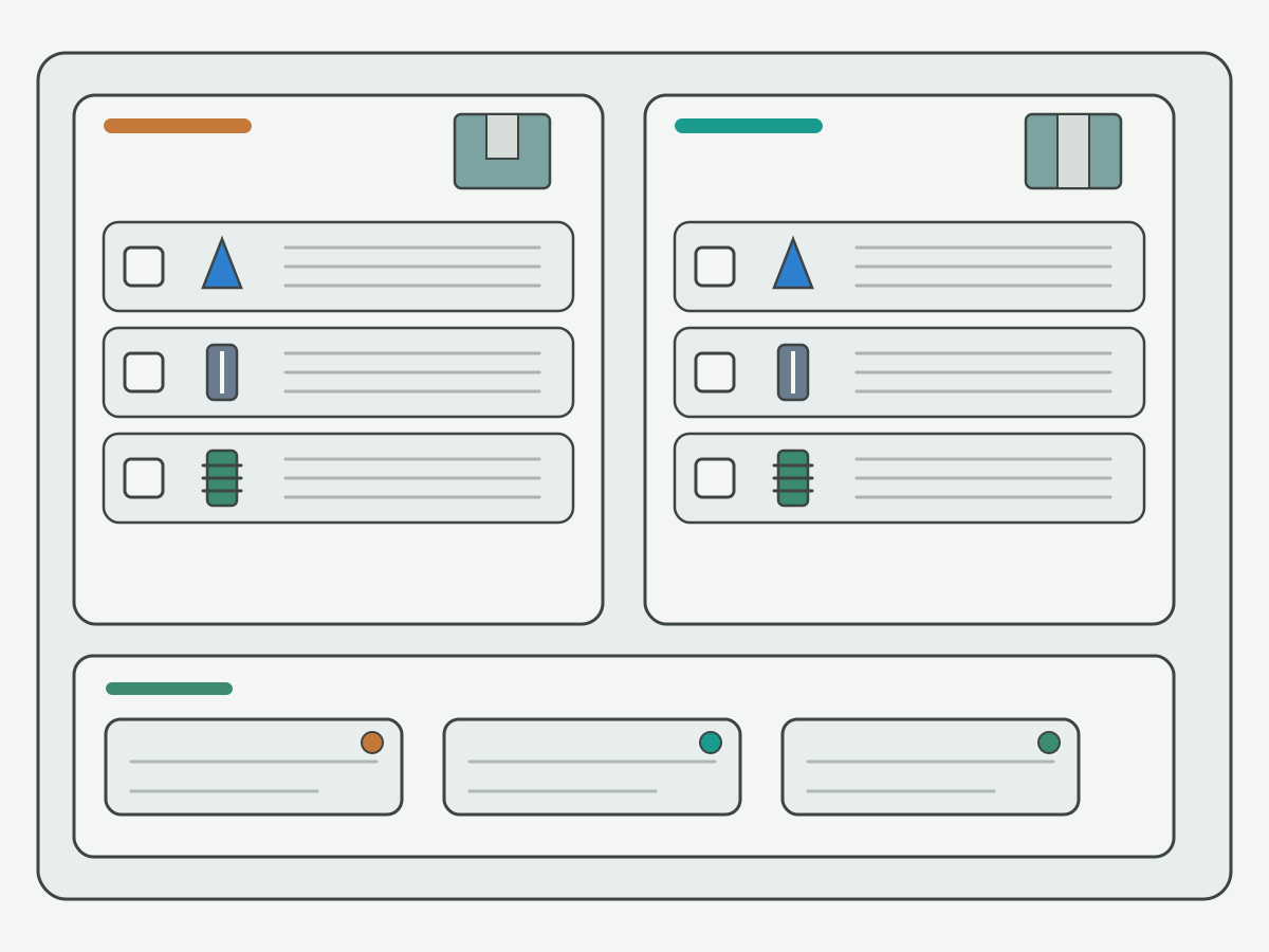
| Field | What to write | Why it matters |
|---|---|---|
| Hole type | Blind or through | Sets exit, chip path, and breakthrough notes |
| Diameter and tolerance | Print size and band (drawing units) | Stops mixed-unit quotes |
| Depth datum and effective depth | From which face; usable length needed | Separates usable length from tip residue |
| Bottom form | Point, flat, or special | Routes conventional point vs flat-bottom review |
| Material | Workpiece family and hardness band if known | Feeds substrate and geometry later |
| Finish steps | Ream, tap, plug, or none | Changes unused depth and chip room |
| Coolant and rigidity | Flood, mist, through-coolant; holder notes | Blind floors often need clearer coolant notes |
| Exit-face notes (through) | Burr, breakout, or sealing requirements | Through holes fail on the exit as often as the entry |
| Quantity or trial window | Prototype, pilot, or production band | Sets review urgency and stock path |
RFQ inputs that usually close a hole-type review:
- Hole type: blind or through
- Diameter, tolerance, and drawing units
- Depth datum, effective depth, and any tip or unused allowance you already know
- Bottom form: point, flat, or special
- Workpiece material and hardness band if known
- Whether a ream, tap, or plug follows
- Coolant style, holder notes, and rigidity or runout notes if known
- Exit-face requirements on through holes
- Quantity or trial window
After the hole-type path is named, open the live solid carbide drill page when solid carbide family geometry is next, or return to the flat-bottom carbide drill page already linked above when a flat usable floor is required. Soft support in the related links covers deep-hole carbide drills, through-coolant solid carbide drills, and stub-versus-jobber length. Indexable drill product pages remain outside this hub until that product path is published.
Process Guide vs Product & Related Pages
| Resource | What it covers | Next step |
|---|---|---|
| This blind vs through hub | Definitions, bottom and effective depth, chip/coolant/exit, drill/ream/tap by hole type, drawing checklist | Finish hole-type checks; do not buy from the definitions alone |
| Flat-bottom carbide drill (product) | Flat-bottom buy and series selection | Open after bottom form needs a flat floor |
| Solid carbide drill (product) | Solid carbide family detail | Optional support after hole type and depth are locked |
| Deep-hole carbide drill (product) | Deep-hole buy path | Use after depth-to-diameter or chip path needs deep-hole tooling |
| Chip shapes and colors | Chip diagnosis | Use when chip clues drive the next process change |
| Peck drilling | When peck is required | Use for packed-chip or depth clearing notes |
| Through-coolant solid carbide | Through-coolant process and product support | Use after coolant reach is the open cell |
| Drill materials (HSS / cobalt / carbide) | Substrate comparison hub | Hole type first here; open materials guide after depth path is locked |
| Drill size chart (when live) | Numbering systems and conversion | Do not copy that full table onto this hub |
Five related search phrases for blind-hole definition map to this one hub. Do not split them into thin synonym pages. Keep buy-select language on the product pages. Keep size-chart depth on the size chart resource when that page is live. Keep materials depth on the live HSS cobalt and carbide drill materials guide rather than rewriting a substrate comparison here. This hub stays on hole type, bottom and depth, chip and exit behavior, drill/ream/tap differences by hole type, and the drawing checklist.
Related Live Links (Hard Links Only)
- Deep-hole carbide drill: deep-hole product support after depth and chip path need it
- Through-coolant solid carbide drill: coolant-reach support after the blind-floor path is named
- Stub vs jobber vs long series drills: length routing after hole type and diameter path are locked
Flat-bottom carbide drill, solid carbide drill, chip shapes, peck drilling, and the materials guide are already linked once in the sections above. Use the RFQ button below when hole type, depth, or finish fields still cannot close from a published series.
Evidence Notes & FAQ
Evidence on this page is the blind-versus-through definition table, the bottom-geometry and effective-depth checklist, the chip/coolant/exit behavior table, the drill/ream/tap-by-hole-type table, and the drawing RFQ field list. No invented customer case studies, life percentages, prices, or HENTRY-measured depth guarantees in millimeters appear here. Confirm shop-dependent cells with application engineering before you lock a process sheet.
Blind Hole vs Through Hole FAQ
What is a blind hole?
A blind hole stops inside the workpiece and has no exit on the far side. Chips and coolant must leave through the entry, flute, or other path the process provides. The definitions section and its figure show blind versus through in section view.
What is the difference between a blind hole and a through hole?
A through hole exits the far face; a blind hole does not. That change affects bottom callouts, effective depth, chip and coolant paths, and breakthrough or exit-burr risk. Use the definitions, depth, and chip sections together before you lock tools.
What is effective depth vs drilled depth?
Effective depth is the usable length from the named datum. Drilled depth often includes tip allowance or unused room below that usable band. Thread usable length is a third callout when a tap follows. This page gives a checklist, not a fixed millimeter conversion guarantee.
When do I need a flat-bottom drill for a blind hole?
When the print needs a flat usable floor, when tip residue would steal required effective depth, or when a plug or seal sits on that floor. A conventional point may still be enough when the print accepts a conical tip residue. Open the flat-bottom carbide drill product page after that drawing decision is named; do not treat flat-bottom as an absolute rule for every blind hole.
How do chip and coolant paths differ in blind vs through holes?
Blind holes must evacuate chips without a far exit, so packing and coolant reach at the floor matter more. Through holes can use the exit path but add breakthrough load and exit-face quality. Chip diagnosis continues on the chip-shapes guide already linked in the chip section.
What drawing info should I list before an RFQ?
List hole type, diameter and tolerance, depth datum and effective depth, bottom form, material, whether a ream or tap follows, coolant and rigidity notes, exit-face requirements on through holes, and quantity or trial window. Leave unknown cells blank. Use the drawing checklist section as the field list.
Can I ream or tap a blind hole the same way as a through hole?
No. Blind reaming and tapping need clear unused depth and chip room at the floor; through operations can use the far exit for chips and breakthrough behavior. Keep reamer encyclopedia depth on dedicated reamer resources, and keep full tap-drill tables on a tap-drill chart when that resource is live.
Where do drill size charts and materials fit after hole-type choice?
Hole type and depth come first on this hub. Size systems and conversion continue on a drill bit size chart resource when that page is live; until then, write the preferred size system on the RFQ. Substrate comparisons among HSS, cobalt, and carbide continue on the materials guide already linked in the process-versus-product section.
Request Custom Cutting Tool Support
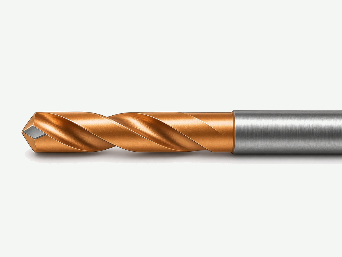
When hole type, bottom form, effective depth, chip path, or finish steps are still open, send the drawing notes through a custom review. HENTRY application engineering can help close hole-type and process fields before you lock a series.