
AI and automation in CNC machining start with sensing, labeled change-outs, and closed-loop actions. They are not a black-box substitute for process engineering. Tool condition monitoring and breakage detection reduce unknown edge failures when a cell runs with less supervision. Wear prediction only becomes useful when material, tool, program, and change-out reasons stay consistent enough to train against. Adaptive cutting may tune feed or load limits inside a safe envelope; it does not replace the right tool, chip evacuation, coolant strategy, or a stable baseline. Lights-out production needs proven process capability, alarm tiers, spare and regrind coverage, and a response SLA before you remove dedicated operators from the cell.
This page is a practical decision framework for process and automation engineers, production engineering, and plant managers who want clearer technical boundaries. It is not a software sales page and it does not invent model accuracy, remaining-life percentages, ROI, or price. Lifecycle economics stay on tool life and tooling economics. Drill wear morphology stays on drill wear types. Speeds, feeds, and chip rules stay on speeds, feeds and chip control. Symptom triage after an alarm stays on CNC machining troubleshooting.
Use this sequence before you buy another monitoring package or schedule unmanned hours:
- Name which signals you will watch and what action each alarm must trigger.
- Separate breakage stop from progressive wear advisories.
- Only trust wear-prediction windows when change-out labels and setup records are consistent.
- Limit adaptive changes to feed, load, or peck rhythm inside an engineering envelope.
- Prove process stability, spare coverage, and response SLA before lights-out.
- Send drawings plus monitoring notes when tooling geometry must support automation.
Monitor · Predict · Adaptive · Lights-out · Checklist · FAQ
What Does Tool Condition Monitoring Actually Watch?
Tool condition monitoring (TCM) connects machine and process sensors to thresholds and actions. Educational process-monitoring literacy explains how spindle load, power, vibration, acoustic emission, motor current, and vision snapshots can flag abnormal cutting states; see this process monitoring education overview. Treat those channels as input principles, not as a promise that every break will be caught.
Common signal families (principle level)
- Spindle load / power: rises with dullness, packing, or engagement mistakes; useful for gradual change and some sudden events when sampled fast enough.
- Vibration: chatter, loose holders, and some fracture events show up as amplitude or frequency shifts; vibration literacy belongs with machining stability education such as this milling vibration reduction overview and this turning vibration reduction overview.
- Acoustic emission / airborne sound: sensitive to edge events in some setups; needs careful placement and noise rejection.
- Motor current / drive data: often available from the CNC without extra sensors; still needs thresholds tuned to the operation.
- Vision / edge photos: offline or in-cell images support wear labels; they are slow for real-time breakage stop unless the architecture is designed for it.
Wear pattern language still matters when you interpret a progressive signal. Third-party wear education such as this tool wear overview, this what is tool wear summary, and this tool wear explanation helps operators name flank wear, chipping, and built-up edge when they label a change-out. Holder runout and imbalance can inject noise into load and vibration channels; toolholding literacy such as this toolholding overview and this tool holder technology overview belongs in the monitoring setup checklist.
Breakage detection versus progressive wear
Breakage detection is a high-priority stop class. Progressive wear is usually a planning class. Mixing them into one soft advisory is a common failure mode for unattended cells.
| Signal intent | Typical time scale | Typical action |
|---|---|---|
| Sudden breakage / missing edge | Milliseconds to seconds | Feed hold or cycle stop; quarantine tool; inspect part and holder |
| Progressive dullness / load drift | Minutes to many cycles | Advisory; schedule change-out; keep recording accepted pieces |
| Chatter / vibration band | Often within a pass | Reduce engagement or stop; do not “adapt forever” into scrap |
| Vision / offline photo trend | Between tools or shifts | Label wear state; feed the prediction or crib decision |
Milling and drilling symptom libraries remain useful when an alarm fires without a clear edge story. See this milling troubleshooting overview, this drilling troubleshooting overview, and this milling troubleshooting guide. After the stop, route human triage through CNC machining troubleshooting rather than treating the monitor as a full diagnosis engine.
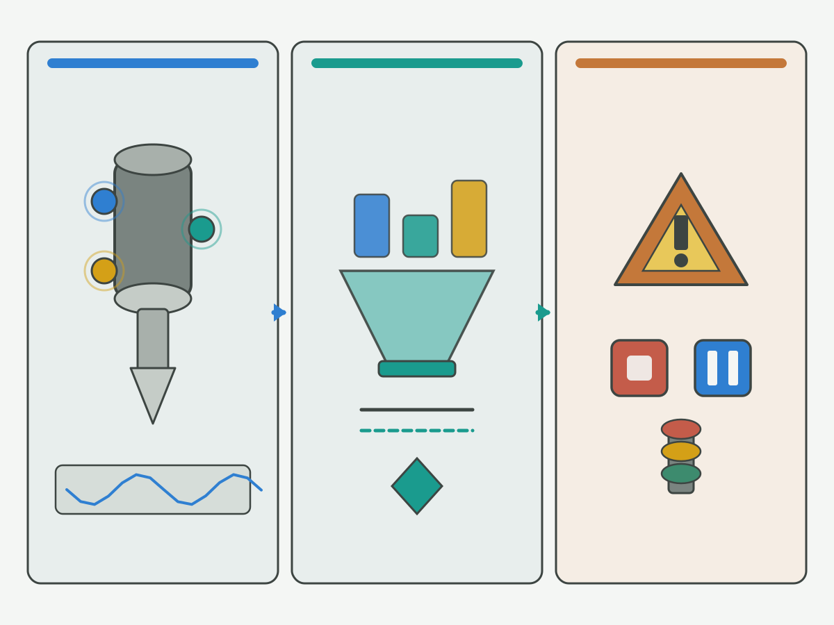
How Honest Is “Tool Wear Prediction”?
Marketing language often implies that a model can state remaining pieces with confidence. On the shop floor, useful prediction is narrower: a change-out window advice under conditions that match the training set. Formal tool-life definitions and formulas, such as this tool life formulas and definitions page, explain controlled-test life. They do not certify an AI remaining-life claim for your cell.
Minimum data before you trust a wear window
- Same workpiece material grade and condition family (or an explicit lot flag when it changes).
- Same tool ID / geometry family, coating, and edge prep; holder and projection recorded.
- Same program structure and engagement strategy for the feature under watch.
- Change-out reason codes: wear limit, size, finish, chip, breakage, scheduled swap.
- Accepted pieces since last edge (or last regrind); scrap or rework tied to that edge.
- Edge photos or load/vibration curves at change-out when the decision is borderline.
Without those labels, a model mostly learns your inconsistency. With them, prediction can suggest when to stage a spare. It still does not guarantee remaining piece counts, life percentages, or “zero breakage.” Shop-record life reading and regrind economics belong on tool life and tooling economics. Drill-specific wear sites that feed labels belong on drill wear types.
What the output should mean
| Output type | Honest use | Not honest |
|---|---|---|
| Change-out window advice | Stage spare; plan crib move | Treat as certified remaining pieces |
| Risk band (low / watch / stop) | Operator or automation policy | Publish as accuracy % or recall claim |
| Photo similarity to past fails | Inspection assist | Skip metrology on critical features |
| Empty numeric cell | Fill later with shop data | Invent life %, ROI, or AUC |
Where Adaptive Cutting Helps and Stops
Adaptive cutting can modulate feed, spindle load limits, or peck rhythm when sensors show the cut is drifting inside a pre-approved envelope. It is a closed-loop tweak on a known process, not a replacement for selecting the right tool or writing a stable baseline. Parameter and chip-control fundamentals stay on speeds, feeds and chip control.
What adaptation may adjust
- Feed within a documented min/max for the feature.
- Spindle load or power ceiling triggers that slow the cut before a hard stop.
- Peck depth or retract rhythm when packing risk is already engineered into the strategy.
- Engagement reductions that stay inside the NC structure you validated.
What adaptation cannot replace
- Wrong tool geometry, coating, or edge prep for the material and feature.
- Packed chips or blocked flutes that need evacuation redesign, not endless feed cuts.
- Wrong coolant method or concentration for the alloy and hole depth.
- Runout, worn holders, or unbalanced assemblies that dominate vibration and size.
- A process that already scrapes tolerance without monitoring.
Coolant and chip behavior set hard limits on how far feed adaptation can go. Fluids literacy such as this coolant know-how overview and this metalworking fluids overview supports that boundary discussion. Finish symptoms that appear when adaptation hides a dull edge belong with machining surface finish checks, not with a higher AI confidence claim.
Hypothetical scenarios (teaching only)
Hypothetical A: breakage stop on an unmanned shift: A cell runs a validated drill cycle with a fast missing-edge stop tied to spindle load spike and a confirmed spare in the changer. Mid-shift, the edge fractures. The control holds feed, parks the tool, and pages the on-call technician. Scrap is limited to the in-cut part. This scenario does not claim a detection rate or “zero breakage.” It shows why breakage class must be harder than wear advisories.
Hypothetical B: unlabeled prediction fails: A plant feeds months of cycle counts into a wear model but never records change-out reason, material lot, or holder projection. The model suggests a long remaining window. The next lot is harder; size drifts early. The failure is data hygiene, not “AI is useless.” Prediction windows need consistent labels before anyone trusts them for lights-out.
Hypothetical C: adaptive feed masks chip evacuation: Adaptive control keeps lowering feed when load rises in a deep hole. Chips are packing. The part eventually seizes or the tool breaks. Adaptation delayed the stop instead of fixing flute packing, coolant delivery, or peck strategy. Adaptive limits must include a stop, not only a softer feed.
Lights-Out Readiness: Manned Versus Unattended Prerequisites
Lights-out manufacturing is a readiness state, not a software checkbox. Industry and research portals such as the CIRP research portal, NIST Engineering Laboratory, NIST intelligent systems division entry, and ISA-95 committee overview discuss automation and manufacturing systems literacy. They do not certify that your cell is ready for unattended hours.
| Prerequisite | Manned shift (typical) | Lights-out / unattended (stricter) |
|---|---|---|
| Process capability on the feature | Operator can catch drift | Proven capability with recorded stop rules |
| Breakage class alarms | Helpful | Required with hard stop and spare policy |
| Wear / life records | Often informal | Consistent labels and change-out codes |
| Chip and coolant control | Operator clears packing | Evacuation must work without babysitting |
| Spare / regrind turnaround | Can borrow across machines | Sized for the unmanned interval |
| Alarm response SLA | Walk to the machine | Remote confirm path and time limit |
| Adaptive envelope | Optional | Documented min/max and stop, not endless soften |
Tool crib and management literacy, such as this tool management overview, supports spare planning. Inventory state discipline still follows the economics guide on tool life and tooling economics.
Lights-Out Readiness and Data Checklist
Use this checklist before you schedule unattended production blocks. Leave numeric targets blank until your plant fills them. Do not invent uptime %, detection accuracy, or ROI.
- Process: feature capability reviewed; known scrap modes listed; baseline speed/feed locked for the monitored ops.
- Tooling geometry: tool and holder combination justified for the feature; first-article and wear criterion agreed.
- Life records: change-out codes, accepted pieces, photos or curves stored for like setups.
- Alarm tiers: breakage = hard stop; wear = advisory with spare stage; vibration/chatter = stop or engagement cut with a floor.
- Chip / coolant: evacuation proven for the unmanned duration; fluid checks on a defined cadence.
- Spares and regrind: spare count covers the interval; awaiting-regrind queue does not steal from spare.
- Remote response: who gets the page, how they confirm, and when the cell must stay down.
- Data hygiene: material lot, tool lot, program revision, and holder ID recorded when they change.
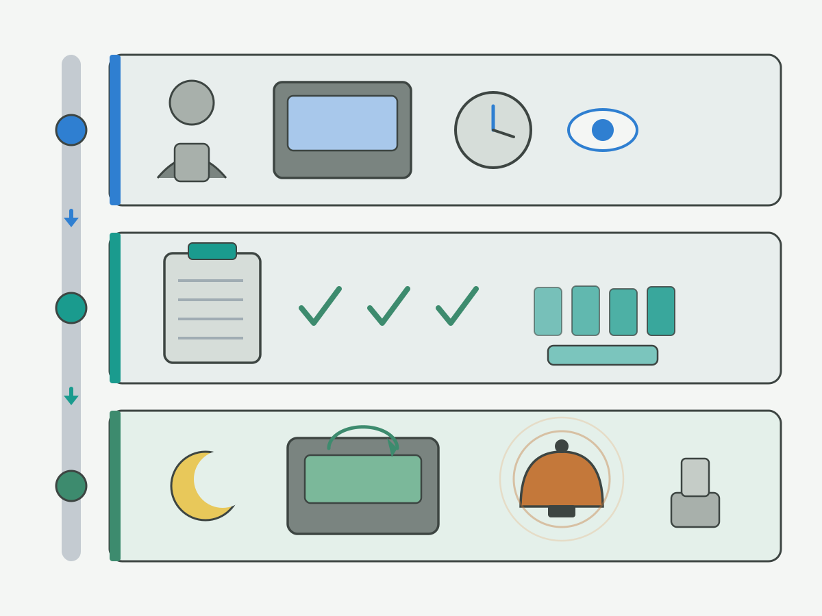
Signal × action map (fill thresholds with your values)
| Signal class | Continue | Reduce feed / engagement | Stop line | Change tool |
|---|---|---|---|---|
| Breakage / missing edge | Default | After stop + inspect | ||
| Progressive load drift | Early band | Optional inside envelope | If envelope floor hit | At shop wear criterion |
| Chatter / vibration band | If validated | If not controlled | If edge damaged | |
| Vision wear label | Low wear | At labeled limit | ||
| Your shop threshold values | Leave blank until tuned |
Tooling Support When You Add Monitoring or Unattended Hours
Stable tooling geometry is a prerequisite for automation, not an afterthought. Selection-stage choices that later affect monitoring noise and regrind paths are organized in the cutting tool selection handbook. Cutting-data literacy portals such as this cutting data notes portal help teams discuss baselines; they do not replace a drawing-tied quotation.
When a solid carbide drilling path is already justified for a monitored hole, product confirmation can use solid carbide drills. When PCD reaming geometry is already justified for a finish feature under size watch, see PCD reamers. Those product links are not first-screen ads and do not replace the RFQ package.
RFQ inputs that make automation-aware tooling quotes usable
- Drawing and revision; material and condition; operation and feature ID.
- Current monitoring method (load, vibration, vision, none) and sample alarm records if available.
- Target manned versus unattended hours (without inventing uptime claims).
- Change-out reason history and edge photos from recent runs.
- Holder / projection, coolant method, and chip issues already seen.
- Inspection criteria you will keep after a tool return or on a new tool.
Discuss Monitoring-Ready Tooling with HENTRY
When you evaluate an HENTRY cutting tool for a cell that already uses or plans tool monitoring, adaptive limits, or unattended blocks, send the drawing together with process monitoring notes and recent change-out history. The next step is to match geometry and inspection to the feature, then agree how wear and breakage will be judged on the floor. No price, MOQ, accuracy percentage, or unverified lead time is stated here.
Send drawing + process monitoring notes for RFQ
Suggested enquiry subject: AI monitoring and tooling review - [material] - [operation]
AI and Automation in CNC Machining FAQ
What is tool condition monitoring in CNC?
Tool condition monitoring connects sensors such as spindle load, power, vibration, acoustic emission, current, or vision to thresholds and actions. It flags abnormal cutting states so the control or crew can continue, slow, stop, or change the tool. It is sensing plus policy, not a black-box replacement for process engineering.
How is breakage detection different from wear prediction?
Breakage detection is a fast stop class for missing or fractured edges. Wear prediction, when honest, is a change-out window advice under consistent labels and setups. Mixing soft wear advisories with hard breakage stops is a common failure mode for unattended cells.
Can AI replace speeds and feeds engineering?
No. Adaptive controls may tune feed or load inside a documented envelope. They cannot replace correct tool geometry, chip evacuation, coolant strategy, or a stable baseline program. Fix the process first; then decide what the loop is allowed to change.
What data do you need before trusting wear prediction?
You need consistent material and tool families, holder and program notes, change-out reason codes, accepted pieces, and preferably edge photos or load curves. Without labels, models learn inconsistency. Even with labels, output is a window advice, not a guaranteed remaining piece count or life percentage.
When is lights-out machining premature?
It is premature when process capability is unproven, breakage alarms are missing or soft, chip evacuation needs constant babysitting, spare and regrind coverage does not match the unmanned interval, or nobody owns a remote response SLA. Software alone does not create readiness.
How do adaptive controls interact with chip evacuation limits?
Lowering feed can delay a stop while chips pack. Adaptive policy needs a floor and a hard stop, plus an evacuation strategy that works without an operator clearing flutes. If packing is the root cause, redesign peck, coolant, or tool geometry instead of softening feed forever.
What should you send a tooling supplier when adding monitoring?
Send the drawing and revision, material and operation, monitoring method and sample alarm notes, recent change-out reasons and edge photos, holder and coolant notes, and the inspection criteria you will use after return or on a new tool. State manned versus unattended intent without inventing uptime or accuracy claims.
When does this page not apply?
One-off prototypes without repeatable setup records, cells with no plan to label change-outs, safety-critical stops that already force full manual attendance, and any request for invented model accuracy, ROI, price, or zero-breakage promises. Drill wear morphology, lifecycle economics, and speeds-feeds formulas each have their own guides.
Sources and Related Automation Tasks
The outbound references support process-monitoring literacy, tool-wear and tool-life definitions, vibration and troubleshooting education, toolholding and fluids boundaries, tool-management practice, and public manufacturing-systems portals cited in the body. Manufacturer-specific data remain tied to their own products. Hypothetical scenarios and empty threshold cells are HENTRY editorial teaching aids, not measured AI performance results. Sources checked for this draft on 20 October 2026 (Asia/Shanghai).
- Process monitoring education overview (third-party education page; linked in body)
- Milling vibration reduction overview (third-party education page; linked in body)
- Turning vibration reduction overview (third-party education page; linked in body)
- Tool wear overview (third-party education page; linked in body)
- What is tool wear summary (third-party education page; linked in body)
- Tool wear explanation (third-party education page; linked in body)
- Toolholding overview (third-party education page; linked in body)
- Tool holder technology overview (third-party education page; linked in body)
- Milling troubleshooting overview (third-party education page; linked in body)
- Drilling troubleshooting overview (third-party education page; linked in body)
- Milling troubleshooting guide (third-party education page; linked in body)
- Tool life formulas and definitions page (third-party education page; linked in body)
- Coolant know-how overview (third-party education page; linked in body)
- Metalworking fluids overview (third-party education page; linked in body)
- CIRP research portal (third-party research society; linked in body)
- NIST Engineering Laboratory (public metrology / manufacturing research entry; linked in body)
- NIST intelligent systems division entry (public smart-manufacturing related entry; linked in body)
- ISA-95 committee overview (public industrial automation standards entry; linked in body)
- Tool management overview (third-party education page; linked in body)
- Cutting data notes portal (third-party tooling education; linked in body)
For lifecycle economics OWN, use tool life and tooling economics. For drill wear OWN, use drill wear types. For parameter and chip OWN, use speeds, feeds and chip control. For alarm triage OWN, use CNC machining troubleshooting. For selection before automation, return to the cutting tool selection handbook.