
Treat cutting tools as a lifecycle cost decision, not a unit-price shopping list. Record wear and accepted-part output on the shop floor, read usable life from those records instead of catalog guarantees, decide regrind versus replace on recoverable geometry, keep crib inventory in clear states, and select suppliers on cost per accepted part plus drawing and regrind closure.
There is no universal guaranteed tool life in hours or piece counts that applies across materials, coolant, holders and process control. PCD and coated carbide also follow different reconditioning paths. This page is a cross-tool economics and management framework. Drill wear morphology stays on its own deep dive; PCD reamer reconditioning stays on its specialty guide.
Use this sequence before you change supplier or stock policy:
- Name the wear signal and the quality symptom on the part.
- Decide continue, schedule regrind or change-out, or stop for root cause.
- Estimate usable output from shop records under the same setup conditions.
- Compare regrind recovery against replacement when geometry still matches the drawing.
- Track active, spare, awaiting-regrind and quarantine tools separately.
- Ask suppliers for lifecycle support and cost per accepted part, not bare unit price alone.
Wear · Life reading · Regrind · Inventory · Suppliers · FAQ
What Tool Wear Signals Matter for Life Decisions?
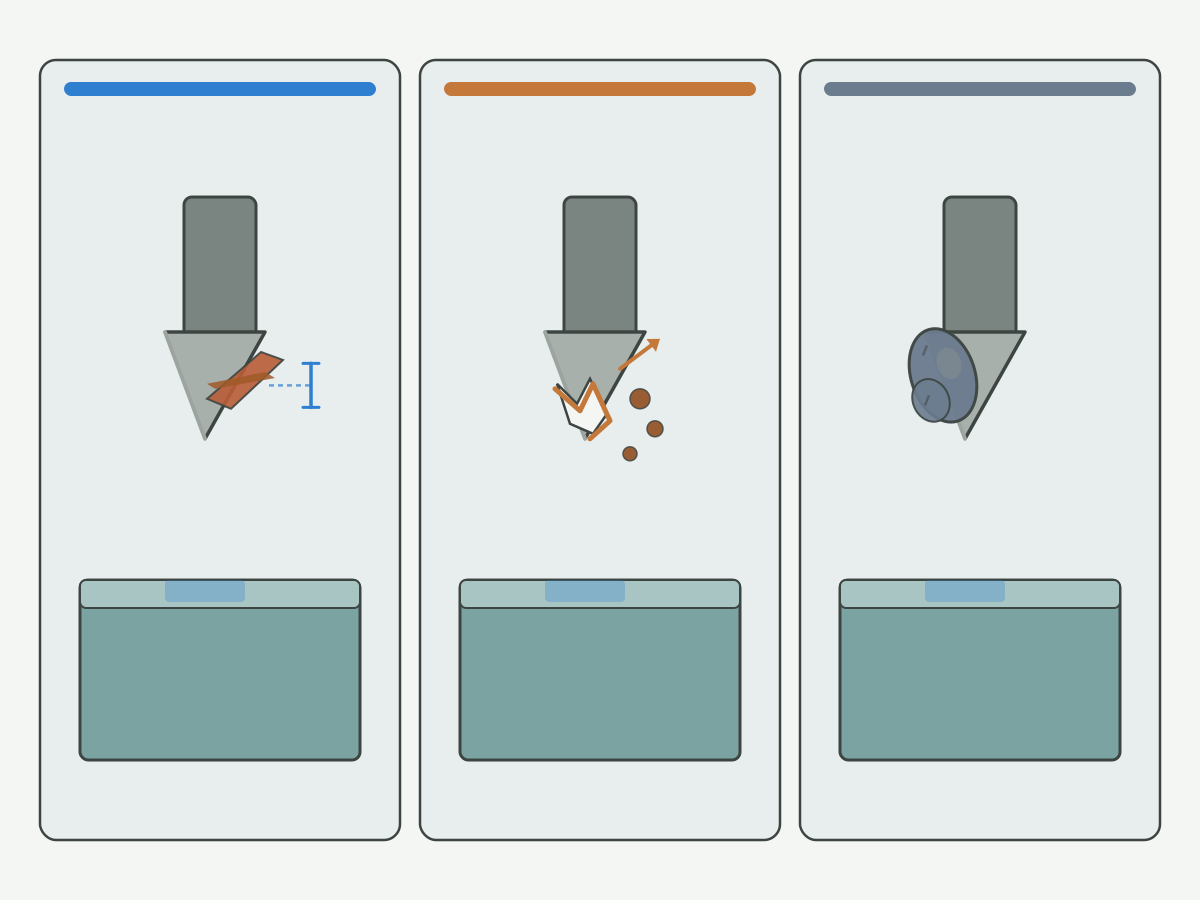
Across drills, end mills, reamers and turning edges, life decisions start from what the edge and the part are telling you. Educational wear overviews describe how progressive flank wear, cratering, built-up edge, chipping and notch wear alter the contact zone; see this tool wear overview and this what is tool wear summary. Use those patterns as inspection language, not as a promise of remaining life.
Wear and quality signals worth recording
- Flank wear: progressive land on the clearance face; often the first signal for a planned change-out when size and finish still hold.
- Chipping or fracture: broken edge or corner; usually a stop-and-inspect event, not a “run a few more parts” choice.
- Built-up edge (BUE): workpiece material adhering to the edge; can mimic dullness and spoil finish while the substrate is still recoverable.
- Size drift: diameter, length or feature size trending toward the tolerance limit under the same program and holder.
- Surface or burr change: finish marks, tear-out or burr growth that appear with the same coolant and feed settings.
Flank-wear education pages such as this flank wear note help separate progressive land wear from sudden edge failure. Complementary wear literacy is also summarized in this tool wear explanation.
Three decision states at the machine
| State | Typical signals | Next action |
|---|---|---|
| Continue | Wear within the shop’s agreed criterion; size and finish still inside limits | Keep running; keep recording pieces and edge photos |
| Schedule regrind or change-out | Wear approaching limit; finish or size trending; edge still intact | Plan change-out or regrind queue; stage a spare |
| Stop and root-cause | Chipping into substrate, crack suspicion, sudden noise/load, scrap spike | Stop; quarantine the tool; check holder, coolant, program and material lot |
Drill-specific wear sites and decision trees belong on drill wear types. Do not treat this economics page as a substitute for that morphology deep dive. Broader symptom triage when vibration, chatter or packing confuse the wear picture stays on CNC machining troubleshooting. Parameter checks that affect wear rate without inventing a life number belong on speeds, feeds and chip control.
How Should You Read Tool Life Without Invented Guarantees?
Catalog starting data and textbook tool-life definitions explain how life is measured under controlled tests. They do not certify the hours or piece count your cell will see. A formal definition and related formulas appear in this tool life formulas and definitions page. Treat published curves as orientation, then build a shop reading from your own records.
Minimum fields to record on every change-out
- Workpiece material grade and condition; operation and feature ID; drawing revision.
- Tool ID / lot; holder and projection; coolant or lubrication method.
- Programmed speed and feed (as run); engagement notes that matter for that op.
- Change-out reason: wear limit, size, finish, chip, breakage, scheduled swap.
- Accepted pieces since last edge (or since last regrind); scrap or rework tied to the edge.
- Regrind count and inspection result after return (pass / fail / limited use).
- Photos of the edge and of the critical feature when the decision is borderline.
Without those fields, “tool life” becomes a story told after a scrap event. With them, you can compare like setups and decide whether a short run is a tool problem, a setup problem or a material-lot problem.
Cost per accepted part framework (fill with your numbers)
Cost per accepted part for tooling is the sum of tool purchase or regrind cost, change-out downtime, and scrap or rework attributable to the edge, divided by accepted pieces under the same setup. Leave cells blank until your finance and production teams fill them. Do not invent hours, piece counts, percentages or ROI here.
| Cost element | Your value (shop fill-in) | Notes |
|---|---|---|
| New tool or insert cost allocated to this edge | Leave blank until purchasing provides the figure | |
| Regrind or recondition cost per return | Include inbound freight if material | |
| Change-out time × burden rate | Use your shop’s approved burden; no default here | |
| Scrap / rework cost tied to worn or broken edge | Only costs you can attribute | |
| Accepted pieces on that edge / after that regrind | From the production record | |
| Cost per accepted part | (sum of attributed costs) ÷ accepted pieces |
Runout and holder condition change how wear develops and how life readings should be interpreted. Toolholding education such as this toolholding overview and this tool holder product and technology overview belong in the setup record when life looks unstable across identical programs. Coolant method literacy that affects edge temperature and BUE risk is summarized in this coolant know-how overview and this metalworking fluids overview.
When Does Regrinding Beat Replacement?
Regrind beats replacement when the remaining blank or edge stock can restore drawing geometry, coating or edge prep can be restored to the process requirement, turnaround and spare inventory cover the outage, and cost per accepted part after return is better than buying new under the same quality target. Regrind loses when cracks reach the substrate, the edge has chipped beyond recoverable stock, geometry cannot return to the drawing, or inspection after grind fails the feature critical to the process.
| Situation | Lean regrind | Lean replace |
|---|---|---|
| Uniform flank wear; edge intact | Yes, if stock and coating path exist | Only if regrind capacity or lead time fails |
| Chipping into substrate / crack suspicion | No | Yes; quarantine and investigate |
| Size still recoverable to drawing after grind | Yes after re-inspect | If grind cannot restore size |
| Coating critical and cannot be restored | Only if uncoated or alternate prep is approved | Often yes |
| One-off prototype with no regrind channel | Usually no | Yes |
Re-inspect after every regrind
A returned tool is not “as new” until inspection says so. Check diameter or form against the drawing, edge prep and coating condition where specified, runout in the intended holder, and a limited first-article cut before releasing the tool to full production. PCD reamer reconditioning, inspection packs and specialty regrind cycles stay on PCD reamer regrind and reconditioning guide; what to require on an inspection pack is on PCD reamer inspection pack requirements. Third-party reconditioning competency overviews such as this tool reconditioning competency page describe process families; they do not set HENTRY guarantees or cycle counts.
In-house versus outsourced regrind (principles only)
- In-house: faster turnaround possible; needs skilled grind capacity, inspection and grit control; still requires documented acceptance criteria.
- Outsourced: useful when volume or specialty geometry exceeds local skill; needs clear drawings, wear photos, agreed inspection and a spare pool sized for transit time.
- Either path: do not state unverified prices, ROI percentages or “guaranteed N regrinds” in planning documents without a signed supplier agreement tied to a specific tool drawing.
Milling and drilling troubleshooting pages help separate wear that regrind can address from process faults that will destroy the next edge. See this milling troubleshooting overview, this drilling troubleshooting overview and this milling troubleshooting guide.
Hypothetical Teaching Scenarios
The following scenarios are hypothetical teaching examples. They are not HENTRY measured tool life, not published case ROI and not guarantees for any material or tool family.
Scenario A (hypothetical): uniform flank wear, geometry recoverable
A coated carbide end mill shows progressive flank wear. Size and finish still pass. The shop photographs the edge, schedules change-out at the agreed wear land, and sends the tool for regrind with the drawing and holder note. After return, inspection confirms diameter and edge prep; a short first-article run passes. Decision: regrind path continues for this SKU while wear stays uniform and the coating path remains approved.
Scenario B (hypothetical): corner chip into substrate
A solid carbide drill chips at the corner after an abnormal load event. The hole shows tear-out. The tool is quarantined. Root-cause checks cover runout, coolant blockage and a material-lot note. Decision: replace the edge; do not regrind a cracked or deeply chipped blank into the same critical hole process until the root cause is closed.
Scenario C (hypothetical): regrind turnaround forces excess spare stock
Regrind transit plus queue time exceeds the production cadence for a high-runner reamer. The crib grows a large “awaiting regrind” pile and an oversized spare pool. Decision: either shorten the regrind channel, approve a qualified second source, or redesign safety stock against measured turnaround, rather than buying more tools without a state map. Macro inventory-cycle commentary for the industry is outside this page; see cutting tool industry report 2026 for that layer.
Tool Inventory and Change-Out Checklist
Tool crib practice fails when every drawer is treated as “available.” Separate physical and system states so planners know what can go to a machine tonight.
| Inventory state | Meaning | May issue to machine? |
|---|---|---|
| Active | On a spindle or staged for the current setup | Already in use; track remaining plan |
| Spare | Inspected, ready, matched to drawing revision | Yes |
| Awaiting regrind | Worn or scheduled; waiting grind or return | No |
| Quarantine | Breakage, crack suspicion, failed inspection, unknown history | No until disposition |
Shop-level tool management articles such as this tool management overview stress identification, location and usage history. Use that literacy to design your four states; do not copy another plant’s stocking percentages.
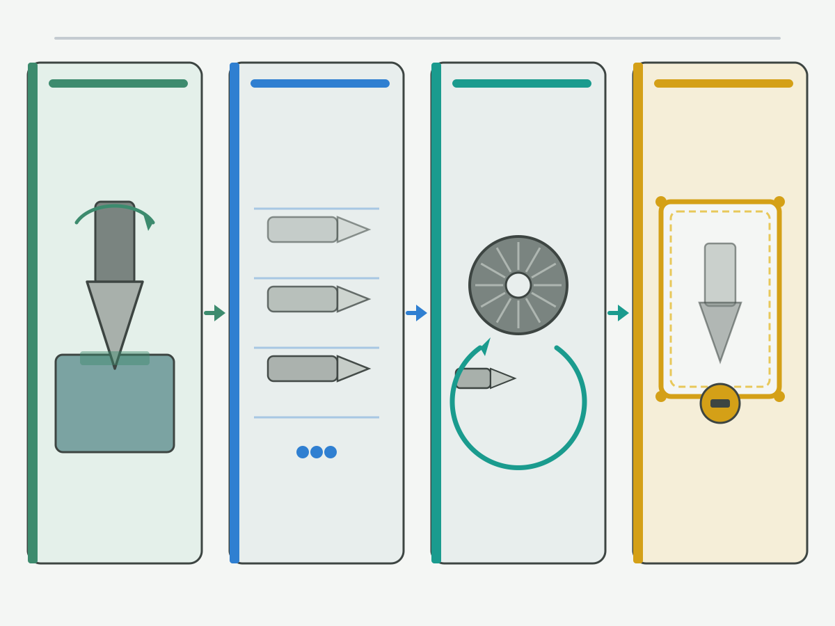
Minimum records and safety stock versus regrind turnaround
- Keep a unique ID or lot for each critical special tool; link it to drawing revision.
- Record issue / return / regrind send / inspection result with date and operator or crib clerk.
- Size spare stock from production cadence and measured regrind turnaround, not from a round “months of stock” slogan.
- When turnaround lengthens, raise awaiting-regrind visibility and spare coverage together; do not hide worn tools in the spare bin.
Change-out, send-to-grind and return checklist
- Change-out: photograph edge and feature if borderline; write reason code; move the tool to awaiting regrind or quarantine; issue a spare with matching revision.
- Send to grind: attach drawing, wear photos, prior grind count if known, coating/edge-prep requirement, and return inspection criteria.
- Return: inspect before restocking as spare; reject into quarantine if criteria fail; update the life record with accepted pieces on the prior run.
- Release: only spare-state tools with a pass record go to the next setup sheet.
Selection-stage geometry choices that later affect life and regrind paths are organized in the cutting tool selection handbook. When a solid carbide drilling path is already justified, product confirmation can use solid carbide drills; when PCD reaming geometry is already justified, see PCD reamers. Those product links are not first-screen ads and do not replace the RFQ package.
How to Select a Cutting Tool Supplier for Lifecycle Support
Unit price alone hides change-out time, scrap risk and regrind closure. Prefer suppliers who can discuss cost per accepted part, drawing control, inspection evidence and regrind or replacement options for the same feature. Distributor-side evaluation of PCD reamer manufacturers stays on how distributors evaluate a PCD reamer manufacturer; this section stays at a general lifecycle scorecard.
| Scorecard dimension | What to ask | What not to invent |
|---|---|---|
| Drawing and revision control | How are changes controlled and labeled on tools? | Do not assume undocumented “same as last ship” |
| Wear and application support | Will they review wear photos and setup notes? | Do not accept a life % without matching conditions |
| Regrind or recondition path | Criteria, inspection, turnaround communication | No guaranteed cycle count without agreement |
| Inspection consistency | What is measured before shipment and after regrind? | Do not skip first-article on critical features |
| Delivery communication | How are delays and lot changes notified? | No unverified MOQ or lead-time claims here |
| Cost per accepted part dialogue | Willingness to use shop records, not only unit price | No fake ROI tables |
RFQ inputs that make lifecycle quotes usable
- Drawing and revision; material and condition; operation description.
- Current wear photos and change-out reason codes from recent runs.
- Production volume rhythm (without inventing a life claim).
- Regrind expectation: in-house, supplier, or none.
- Holder / projection and coolant method when they affect geometry choice.
- Quality targets: size, finish, burr, and the wear criterion you already use.
Cutting-data and application-note portals such as this cutting data notes portal and research entry points such as the CIRP research portal and NIST Engineering Laboratory support literacy; they do not replace your shop record or an HENTRY quotation tied to a drawing.
Discuss Lifecycle Tooling with HENTRY
When you evaluate an HENTRY cutting tool for wear life, regrind support or crib planning, send the drawing together with wear photos and production volume context. The next step is to match geometry and inspection to the feature, then agree how regrind or replacement will be judged. No price, MOQ or unverified lead time is stated here.
Send drawing + wear photos + production volume for RFQ
Suggested enquiry subject: Tool life and regrind review - [material] - [operation]
Tool Life and Tooling Economics FAQ
How do you calculate tool life without a catalog guarantee?
Use shop records under a defined setup: material, tool ID, holder, coolant, program settings, change-out reason and accepted pieces. Compare like conditions. Catalog or textbook life curves are orientation only; they do not certify your cell’s output.
When should you regrind instead of replace a cutting tool?
Regrind when geometry can return to the drawing, the edge is free of crack or deep substrate chip risk, coating or edge prep can meet the process need, and turnaround plus spares cover production. Replace when recovery is unsafe or inspection after grind fails.
What inventory states should a tool crib track?
At minimum track active, spare, awaiting regrind and quarantine. Only spare tools with a pass inspection should issue to a machine. Do not store worn or unknown tools in the spare location.
How do regrind turnaround times affect safety stock?
Longer turnaround raises the spare coverage needed for the same production cadence. Measure transit and queue time, then size spares against that interval. Growing an awaiting-regrind pile without adjusting spares hides risk until a line stops.
What is cost per accepted part for tooling?
It is attributed tooling cost, including purchase or regrind, change-out burden and scrap or rework tied to the edge, divided by accepted pieces under the same setup. Leave numeric cells blank until your shop provides the figures. It is not the same as unit purchase price alone.
What should you send a supplier for a regrind or replacement RFQ?
Send the drawing and revision, material and operation, wear photos, recent change-out reasons, volume rhythm, holder and coolant notes when relevant, and the inspection criteria you will use after return or on a new tool.
How is drill wear diagnosis different from this economics guide?
Drill wear diagnosis maps wear sites and hole symptoms for drills in detail. This guide covers cross-tool life reading, regrind economics, crib states and supplier selection. Use the drill wear page when the question is morphology on a drill.
When does this guidance not apply?
One-off prototypes without a regrind channel, uncontrolled processes with no repeatable setup record, and situations where safety or crack risk already forces scrap of the blank. Also pause life comparisons when material lot, holder or program changed without being recorded.
Sources and Related Lifecycle Tasks
The outbound references support tool-wear definitions, troubleshooting, reconditioning literacy, toolholding and fluids, tool-management practice and research portals cited in the body. Manufacturer-specific data remain tied to their own products. Scenarios and empty cost tables are HENTRY editorial teaching aids, not measured performance results. Sources checked for this draft on 20 October 2026 (Asia/Shanghai).
- Tool wear overview (third-party education page; linked in body)
- What is tool wear summary (third-party education page; linked in body)
- Flank wear note (third-party education page; linked in body)
- Tool wear explanation (third-party education page; linked in body)
- Tool life formulas and definitions page (third-party education page; linked in body)
- Toolholding overview (third-party education page; linked in body)
- Tool holder product and technology overview (third-party education page; linked in body)
- Coolant know-how overview (third-party education page; linked in body)
- Metalworking fluids overview (third-party education page; linked in body)
- Tool reconditioning competency page (third-party education page; linked in body)
- Milling troubleshooting overview (third-party education page; linked in body)
- Drilling troubleshooting overview (third-party education page; linked in body)
- Milling troubleshooting guide (third-party education page; linked in body)
- Tool management overview (third-party education page; linked in body)
- Cutting data notes portal (third-party tooling education; linked in body)
- CIRP research portal (third-party research society; linked in body)
- NIST Engineering Laboratory (public metrology / manufacturing research entry; linked in body)
For drill wear OWN, use drill wear types. For PCD reamer reconditioning OWN, use PCD reamer regrind and reconditioning guide. For distributor evaluation OWN, use how distributors evaluate a PCD reamer manufacturer. For selection before life economics, return to the cutting tool selection handbook. For tool condition monitoring, adaptive cutting limits and lights-out readiness after life records exist, see AI and automation in CNC machining.