
There is no single best drill bit for every stainless steel job. Shortlist candidates by material grade and condition, hole requirements, machine rigidity, holder runout, coating and coolant delivery, then prove the choice on a recorded trial before you release production.
This HENTRY guide owns conditional candidate screening, geometry and coolant checklist reading, initial parameter lookup discipline, a short poor-results entry, and a fillable trial record. It is not a drill-material encyclopedia, not a full architecture comparison, and not a full drilling fault hub. Work-hardening glaze and re-entry habits stay on the sibling carbide drill stainless work-hardening playbook. Symptom triage for breakage, chatter, and size faults stays on CNC machining troubleshooting. Milling is supportive only on this page.
Drill types · Workpiece & machine · Geometry · Coating & coolant · Initial conditions · Poor results · Trial confirmation · FAQ
Which Drill Types Should You Consider for Stainless Steel?
Start with the architectures that usually appear on stainless holemaking travelers, then decide from the application, not from a material label alone. Public drill-selection overviews that separate workpiece demands from tool family choices are useful as structure checklists; see this drill selection overview. Hard cutting-material application groups used across the industry are classified in the current ISO hard cutting material application classification. Neither source replaces your series datasheet or your trial record.
HSS-Co and Solid Carbide: Compare the Application, Not Just the Material
HSS-Co means a cobalt-bearing high-speed steel substrate family. It is not a coating name and must not be mixed with coating color talk. Solid carbide drills bring higher hot hardness and often higher productive cutting speeds when the machine, holder, and part support can hold the edge in cut. Cobalt HSS is not universally better for stainless, and carbide is not universally better either.
Compare the real job:
- Machine rigidity, available spindle speed and torque, and how far the tool sticks out.
- Holder type, measured runout location, and clamping reliability.
- Batch size, cycle-time pressure, and how often tools can be changed safely.
- Hole quality (size, position, finish, burr) and what happens after the hole (ream, bore, tap).
- Coolant type and whether through-tool delivery is actually available at the spindle.
If the present tool already meets size, life, and cycle targets on a stable traveler, do not change it only because a catalog label sounds newer. Deeper substrate literacy (HSS, cobalt HSS, carbide) lives on drill bit materials HSS cobalt carbide. Broader metal drill type discovery lives on drill bit types for metal CNC.
When Another Drill Architecture Needs Evaluation
Exchangeable-head drills, indexable drills, and dedicated deep-hole systems belong on the shortlist only when the diameter, depth ratio, entry condition, or productivity story makes a solid shank awkward. Confirm manufacturer application limits before you treat any architecture as available on your floor. HENTRY supply confirmation is separate from market comparison.
When an indexable path is already under discussion for the diameter and setup, open the live indexable drills product page for series checking. For deeper solid carbide depth or through-coolant need, open deep hole carbide drills or through coolant carbide drills only after depth and coolant path facts are written down. Architecture discovery pages that list drill families without promising your stainless result include this drill selection architecture overview.
| Actual conditions | Candidate direction | Must confirm | Next step |
|---|---|---|---|
| Good rigidity, repeating production, stable coolant | Material-matched solid carbide drill series | Hole quality, depth ratio, coolant delivery, series material group | Check product page, then run a recorded trial |
| Smaller batch or limited machine capability | Compare suitable HSS-Co and carbide options on the same task | Quality, cycle, clamping, usable speed range | Same-task comparison, not a label swap |
| Special depth, interrupted entry, or large diameter productivity need | Dedicated deep-hole, through-coolant, exchangeable-head, or indexable path | Manufacturer application boundary and HENTRY supply scope | Engineering confirmation before purchase release |
This table screens candidates. It is not a purchase-release document.
Which Workpiece and Machine Details Change the Selection?
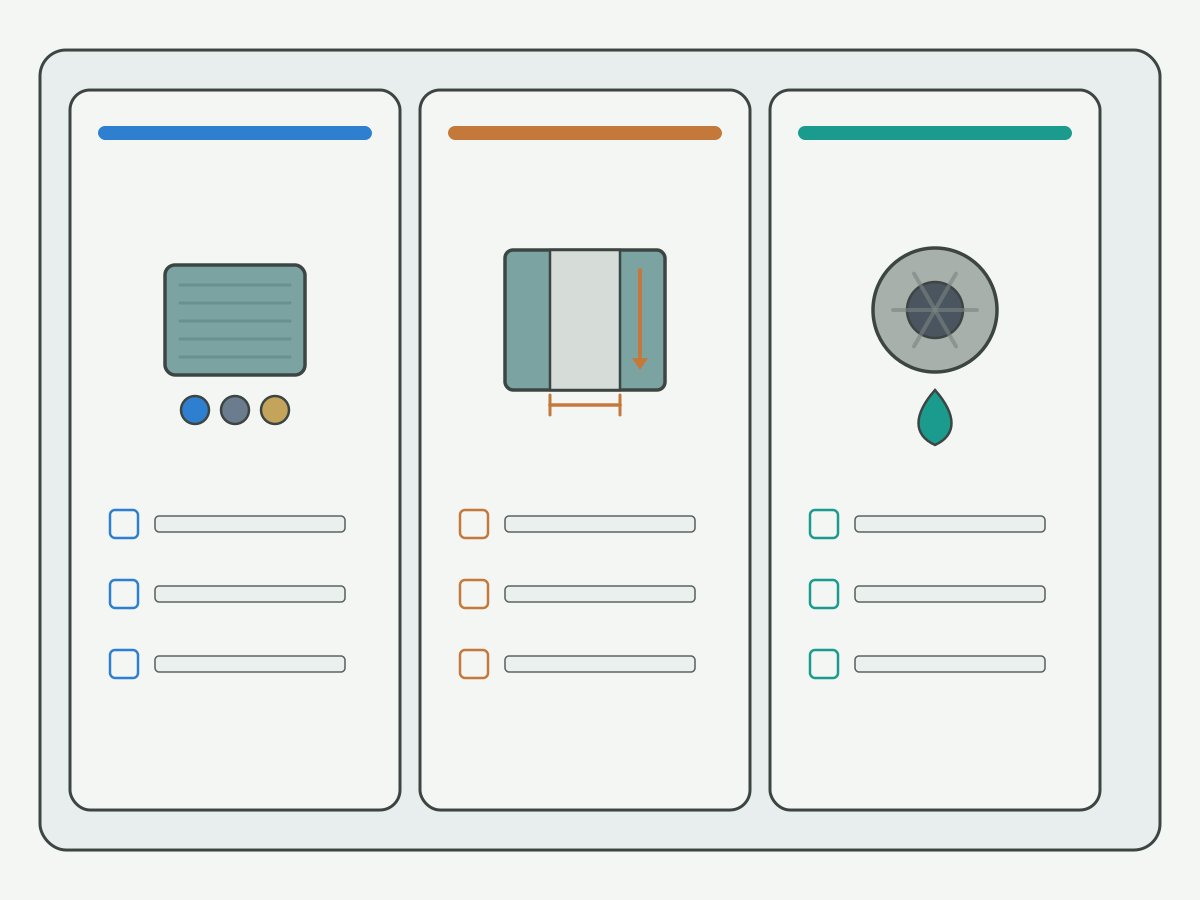
Turn abstract “stainless is hard to drill” talk into fields you can write on a traveler. Stainless workpiece-group overviews that stress grade and condition differences (not one recipe for all stainless) include this stainless steel workpiece material group overview. Practical stainless machining checklists that keep heat, work hardening, and process stability in view include this stainless steel machining considerations overview.
Confirm the Stainless Steel Grade and Material Condition
Record the actual grade and heat or lot identity when available. Note heat treatment, hardness or cold-work state, and whether the surface already carries machining hardening from a prior pass. Do not copy one unverified parameter set from 304 onto 316 or onto a duplex grade. If glaze and re-entry risk is already the open problem, jump to the work-hardening playbook linked in the opening instead of stretching this selection page into a glaze playbook.
Define the Hole, Depth and Quality Requirements
Write diameter, tolerance, position, and surface needs. Separate through-holes from blind holes and record the usable cylindrical depth. Flag angled entry, exit breakout, cross-holes, and thin walls. Note whether the hole must later be reamed, bored, or tapped. Diameter charts for size literacy (not stainless capability claims) live on related size-chart pages when you need nominal size lookup; this page does not embed a full size chart.
Check Machine, Holder and Coolant Capability
Confirm usable spindle speed, feed, and torque. Measure runout at a stated location and record stick-out. Confirm workpiece support. Verify actual coolant delivery and filtration, not only what the tool catalog assumes. Series-by-material decision pages such as choose carbide drill series by material help after these inputs exist; they do not replace the input sheet.
| Selection input | What to capture | If missing |
|---|---|---|
| Material | Grade, lot/heat if known, hardness or cold-work note | Blocks series confirmation and parameter lookup |
| Hole | Diameter, depth, through/blind, tolerance, position, finish | Blocks geometry and length selection |
| Entry / features | Angle, cross-hole, thin wall, exit condition | Blocks point and pilot decisions |
| Machine / holder | Speed/torque range, runout location, stick-out, support | Blocks HSS-Co vs carbide productivity claims |
| Coolant | External vs through-tool path, pressure/flow if measured, filtration | Blocks coating and internal-coolant tool release |
| Quantity / quality gate | Batch size, acceptance stops, post operations | Blocks trial scope and cost-per-good-hole framing |
Output: a filled selection input sheet. Missing critical fields must be named as blockers before anyone confirms a catalog size.
How Should You Evaluate Drill Geometry?
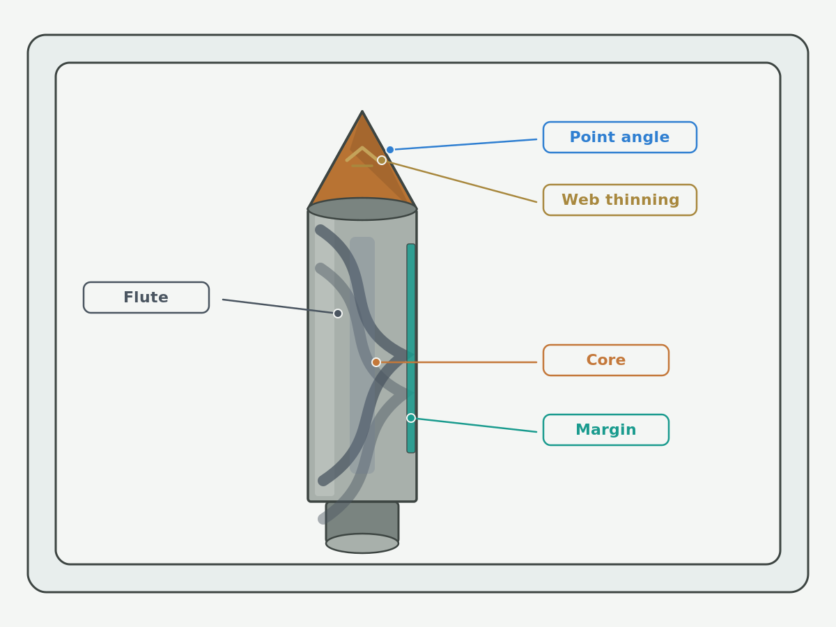
Read the drawing and the series datasheet together. Do not invent a custom point by stacking a few public angles. Educational discussions of drill point features (point angle, web, margins) help you name what to check; see this drill point geometry education overview. HENTRY solid-carbide geometry deep dive lives on solid carbide drill geometry.
Point Angle and Web Thinning
Point angle and web thinning answer different questions. Point angle interacts with entry shape, centering behavior, and thrust. Web thinning changes chisel length and how the center engages. Check them together with entry condition, how the hole is centered, and whether a pilot is required by the series or the process plan. This page does not promise one point angle for all stainless grades. It also does not assume every stainless hole needs a center drill or a pilot.
Helix, Flute Space and Core Thickness
Helix angle, flute volume, and core thickness trade chip space against stiffness. Read the series depth and material range before you assume a “more open flute” always wins on stainless. Do not apply a universal core-thickness ratio across diameters and series. Do not claim that one helix style removes all vibration.
Margins, Edge Preparation and Usable Length
Margins and edge preparation change guidance, heat, and how the wall looks after exit. Separate overall length, flute length, and allowable drilling depth. Match length to the hole and the stick-out risk. “Longer is more universal” is not a purchasing rule. Shop drilling tip checklists that keep geometry, entry, and chip flow in one view include this drilling tips and techniques overview.
How Do Coating and Coolant Affect the Choice?
Coating and coolant only make sense as part of a complete tool specification matched to your delivery path. Coating name ranking tables are out of scope here; coating literacy belongs on drill bit coatings explained.
Check the Complete Tool Specification
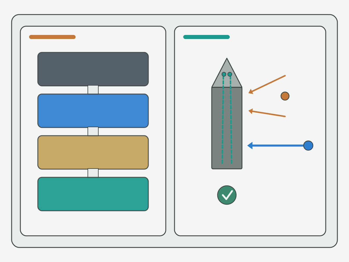
Evaluate substrate, geometry, edge preparation, coating, and surface condition as one package. Confirm material applicability from the series document, not from coating color. Heat-resistance language in a coating blurb is not a dry-drilling permit. Manufacturer pages that present stainless drilling as a combined substrate-geometry-coating design can be used as instances of that documentation style; they do not prove HENTRY tools share the same measured performance. After your grade, hole, and coolant inputs already point to a stainless-oriented carbide path, open the live carbide drills for stainless steel product page to check series and sizes. General solid carbide drill families also live on solid carbide drills when the stainless-specific page is not the right match.
Verify Coolant Delivery at the Application Level
An internal-coolant tool design is not the same as coolant actually reaching the cutting edge through your holder and spindle path. Confirm tool coolant holes, holder through-path, rotary union or spindle capability, and any filtration limits. Judge external flood by depth and chip evacuation risk. Pressure, flow, and concentration numbers belong only when your application data or approved process sheet supplies them. Coolant application discipline for drilling (through-tool versus external choices) is organized in this coolant application in drilling overview. Chip packing risk during holemaking is discussed in this chip control in drilling overview.
How Should You Set the Initial Cutting Conditions?
Selection is incomplete until you know how to read starting data for the exact tool and material, and how to change the cycle without guessing. Detailed HENTRY parameter-process literacy lives on carbide drill speeds and feeds. This page does not publish a universal stainless SFM table for all diameters and substrates.
Start with Data for the Exact Tool and Material
Before the first cut, record:
- Tool series, size, and datasheet revision.
- Material grade and condition.
- Cutting speed (Vc) and feed per revolution (f) from that datasheet for that material group.
- Coolant and cycle requirements stated for the series.
- The stated application range (depth ratio, hole type, machine class notes).
When you need spindle speed or feed rate arithmetic, keep the quantities separate. The following is a calculation example only. It is not a recommendation for any stainless grade or HENTRY tool.
| Quantity | Symbol | Example input (illustration only) | Example result (illustration only) |
|---|---|---|---|
| Cutting speed | Vc | Assume 80 m/min from a datasheet row for a named series/material group | Given by datasheet; do not invent |
| Spindle speed | n | Vc = 80 m/min, diameter D = 10 mm | n = (1000 × Vc) / (π × D) ≈ 2546 rev/min |
| Feed per revolution | f | Assume 0.15 mm/rev from the same datasheet row | Given by datasheet; do not invent |
| Feed rate | vf | n ≈ 2546 rev/min, f = 0.15 mm/rev | vf = n × f ≈ 382 mm/min |
Formula literacy for drilling quantities (definitions of speed, feed, and related terms) is summarized in this drilling formulas and definitions overview. Unit and starting-point literacy for speeds and feeds (still not a stainless guarantee table) includes this speeds and feeds 101 overview and this cutting speed definition calculator. Always prefer the series datasheet numbers for your tool and material group over any public example.
Confirm the Drilling Cycle Before Changing Parameters
Check pilot or guided entry, approach, through-break or blind bottom, and retract rules before you chase numbers. Continuous drilling versus pecking follows the tool instructions and engineering judgment for depth, chip form, and coolant. Pecking is not automatically required for every deep stainless hole. When pecking is already the open question, use peck drilling when required. Do not treat “lower speed” or “lower feed” as the shared answer to every anomaly. When you adjust under control, write why you changed, what the actual conditions were, and what inspection showed.
What Should You Check When Drilling Results Are Poor?
Keep this section short. Collect evidence before you swap tools. Suspected causes are not diagnoses. Full symptom triage stays on the troubleshooting hub already linked above. Wear-pattern literacy that helps you describe edge state without inventing life percentages includes this tool wear understanding overview. Broader drilling fault-structure reading (still not a rewrite of HENTRY triage) includes this drilling troubleshooting overview.
| Phenomenon | Evidence to collect first | Action on this page |
|---|---|---|
| Oversize or unstable diameter | Measurement method, runout, edge state, clamping, process record | Verify causes before deciding on a tool change; size-fault deep dive may need oversized-hole diagnosis pages when still in drilling |
| Life drops suddenly | Wear location, material condition, actual parameters, coolant delivery | Compare against the series requirements; do not invent a life % |
| Chip packing or abnormal load | Chip form, depth, flute type, cycle record | Stop under the stop criteria; clear the evacuation path |
| Entry walk or offset | Entry shape, centering method, stick-out, clamping | Separate tool walk from clamp slip before reselection |
Breakage patterns that need a dedicated entry can open why solid carbide drills break. Oversize with a new carbide drill may need oversized holes new carbide drill diagnosis. Neither page merges into this selection guide.
How Do You Confirm the Selection Before Production?
A shortlist is not a release. Define acceptance and stop rules, then compare candidates on the same task.

Define Acceptance and Stop Criteria Before the Trial
Write hole quality, burr, life expectation window, and cycle targets in measurable language. Name the gauges, measure positions, and record format. Pre-define stop conditions for breakage, chip packing, abnormal load, and quality out-of-limit. Define what “conditional pass” means and who owns the decision.
Compare Candidates on the Same Task
Use the same workpiece requirements and the same acceptance language. Give each candidate its own applicable parameters and write the differences down. One acceptable hole is not production stability. Score three options explicitly: keep the current tool, adjust the current tool, or change to a new candidate.
Frame cost as cost per good hole. Include tool spend, spindle time, and stoppage in one story so none of those lines are counted twice as separate “savings.”
| Field | What to capture | Result / entry |
|---|---|---|
| Material | Grade, condition, lot/heat if known | |
| Tool | Series, size, coating/edge note, datasheet revision | |
| Machine / holder / coolant | Runout location, stick-out, coolant path, measured delivery if any | |
| Hole requirements | Diameter, depth, tolerance, position, finish, post ops | |
| Initial conditions | Vc, n, f, vf, cycle (continuous / peck notes) | |
| Acceptance criteria | Quality gates and stop rules | |
| Results | Measured holes, life window observations, cycle time | |
| Abnormal events | Chip pack, load spike, walk, breakage | |
| Actions | Parameter change, fixture change, tool change | |
| Release scope | Pass / fail / conditional; owner; limits of release |
Leave result cells blank on the floor until measured. A separate downloadable form is not claimed until a tested file exists.
Drill Bits for Stainless Steel FAQ
Are cobalt or carbide drills better for stainless steel?
Neither is universally better. Compare machine rigidity, holder runout, batch size, hole quality, and coolant delivery. Cobalt HSS is a substrate family, not a coating. If the current tool already meets quality and life targets, do not change it only because of a material label.
Can the same drill be used for 304 and 316 stainless steel?
Only when the series datasheet lists both material conditions and you confirm parameters separately for each grade and state. Do not copy one unverified parameter set from 304 onto 316. Heat treatment and cold work can matter as much as the grade name.
What point angle and coating should I choose?
Judge point angle with web thinning, entry condition, and centering method as part of the full tool design. Judge coating with substrate, geometry, edge preparation, and coolant delivery. Do not pick a single public angle or a coating color as a universal stainless rule.
Is peck drilling always necessary?
No. Choose continuous drilling or pecking from the tool instructions, hole depth, chip form, and coolant delivery. Pecking is not an automatic rule for every deep stainless hole. Record the cycle you actually ran on the trial sheet.
When does this guide not apply?
Micro-drilling, dedicated deep-hole systems outside the series scope, special hardened or heavily cold-worked states, and heavily interrupted entries need separate engineering confirmation. Work-hardening glaze and re-entry habits belong on the stainless work-hardening playbook. Full fault triage belongs on the CNC machining troubleshooting hub.
What information should I send to HENTRY?
Send material grade and condition, hole diameter and depth, quality targets, machine and coolant notes, quantity, and the current problem statement. For fault jobs, add current parameters and inspection records. Drawing handling follows the live RFQ process; do not assume attachment formats beyond what the form accepts.
Should I change tools as soon as diameter goes out of tolerance?
No. First collect measurement method, runout, edge state, clamping, and process records. Confirm whether the fault is tool wear, setup, material condition, or cycle related. Change tools only after the evidence points that way, and keep the decision on the trial record.
How should cost be compared between candidates?
Compare cost per good hole under the same acceptance rules. Include tool cost, machining time, and stoppage in one total so those lines are not double-counted. One good trial hole is not enough to claim production cost.
Discuss Your Stainless Steel Drilling Application with HENTRY
When the selection inputs and trial fields still leave an open tooling question, send the package through Discuss Your Stainless Steel Drilling Application. Include material condition, hole diameter and depth, quality targets, machine and coolant notes, quantity, and current issues. For fault jobs, add parameters and inspection records. Drawings follow existing confidentiality handling on the live form. Quotation turnaround after complete drawing information is typically 1 to 2 working days (quotation only, not a delivery or lead-time promise). Attachment limits follow the live form; unused formats are not promised here.