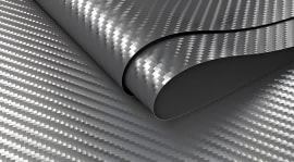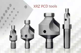
Challenges in carbon fiber reinforced polymer (CFRP) processing: How PCD tools can double the production efficiency of CFRP
H2-1: What Are PCD Tools? Understanding Polycrystalline Diamond Cutters
Polycrystalline Diamond (PCD) tools represent a pinnacle of material science in modern cutting technology. PCD is a synthesized composite material created by sintering diamond particles together under ultra-high pressure and temperature (HPHT) in the presence of a solvent metal catalyst, typically cobalt. The result is an intergrown diamond structure bonded onto a tough cemented carbide substrate.
| Structure Overview: PCD tools integrate an extreme-hardness top diamond layer (~8,000 HV) with a durable tungsten carbide base. This dual-structure provides high wear resistance while maintaining structural toughness and brazeability. |
To truly understand PCD tools, it helps to distinguish them from other cutting materials:
· PCD vs. Monocrystalline Diamond (MCD): MCD consists of a single continuous crystal structure. While MCD achieves absolute atomic sharpness ideal for ultra-precision mirror finishing, it lacks multi-directional fracture toughness. PCD’s randomly oriented grain structure redirects cracks, making it significantly more resistant to mechanical shock.
· PCD vs. Tungsten Carbide: Standard tungsten carbide tools offer good toughness but wear down rapidly when facing highly abrasive non-metallic or composite materials. PCD boasts a hardness of around 8,000 HV (Vickers hardness)—nearly four to five times that of carbide—alongside thermal conductivity that is up to five times higher.
For tool distributors and high-volume machine shops, PCD provides an unbeatable combination: the extreme hardness and thermal dissipation of diamond, backed by the structural support and brazeability of a tungsten carbide body.
H2-2: Key Advantages and Industry Applications of PCD Tooling
The standout characteristics of PCD tooling—unmatched abrasion resistance, rapid thermal dissipation, and low friction—make it the premier choice for difficult-to-machine non-ferrous materials.
Key Advantages in CFRP Machining
Machining Carbon Fiber Reinforced Polymer (CFRP) presents severe challenges. The abrasive nature of carbon fibers rapidly dulls standard carbide edges. As an edge dulls, cutting forces spike, causing severe delamination, fiber pull-out, and matrix burning.
PCD tool edges remain razor-sharp throughout prolonged production runs. This consistent sharpness cleanly shears carbon fibers rather than tearing them, maintaining precise hole and edge tolerances while eliminating costly scrap rates.
Primary Industry Applications
· Aerospace Composites: Precision drilling and routing of CFRP wing skins, fuselage panels, and Nomex/Kevlar honeycomb sandwich structures where delamination is unacceptable.
· Automotive Manufacturing: High-speed milling of aluminum engine blocks, cylinder heads, transmission housings, and structural CFRP components for lightweight vehicles.
· Woodworking & Plastics: High-volume edge-banding and routing of dense MDF, particleboard, and abrasive reinforced plastics.
| Operational Limitation: PCD cannot be used to machine ferrous metals (such as steel or cast iron). At temperatures above 700°C, iron acts as a catalyst, causing diamond's carbon atoms to transform into graphite (graphitization), leading to catastrophic tool failure. |
H2-3: How to Choose the Right PCD Tool for Your Machining Needs
Selecting the correct PCD tooling requires evaluating workpiece geometry, material structure, and production volume to balance upfront investment against cost-per-part savings.
1. Tool Architecture: Braze-Tip vs. Solid/Full-Top PCD
· Brazed-Tip PCD: A PCD segment is brazed onto a carbide body pocket. This is the most cost-effective construction for large-diameter mills, drills, and routing bits.
· Solid / Full-Top PCD: The entire cutting end is solid PCD sintered to a carbide shank. Essential for small-diameter tooling (under 3mm) or high-aspect-ratio deep-hole drilling where braze seams could fail under stress.
2. Geometry Optimization for CFRP
· Compression Routers (Up-Cut / Down-Cut): Combine opposing helix angles to force top and bottom surface fibers toward the middle of the laminate, neutralizing burrs and fraying.
· Double-Point Angle / Brad-Point Drills: Feature a sharp center point to prevent tool wandering, paired with a secondary angle (e.g., 130°/80°) that shears outer fibers before breaking through the back face, preventing exit delamination.
PCD Tooling Selection Matrix:
| Tool Type | Best Suited For | Primary Benefit |
| PCD Compression Router | CFRP panel profiling, edge trimming | Prevents top/bottom surface fraying |
| PCD Brad-Point Drill | Thin CFRP laminates, sandwich panels | Eliminates exit delamination |
| PCD/Carbide Step Drill | CFRP-to-Titanium stack drilling | Combines PCD sharpness with impact resistance |
While standard carbide tools carry a lower initial purchase price, PCD tools consistently deliver 10x to 50x longer tool life. For high-volume automotive suppliers or composite machine shops, the reduced machine downtime and lower scrap rate yield a lower total cost per part.
H2-4: Optimizing Performance: Speeds, Feeds, and Maintenance for PCD Tools
Maximizing return on investment with PCD tooling depends on adhering to proper cutting parameters and maintenance schedules.
Recommended Cutting Parameters
· CFRP & Composites: Cutting Speed (Vc): 200 – 600 m/min | Feed per Tooth (fz): 0.03 – 0.12 mm/tooth. Note: CFRP is best machined dry or with high-vacuum dust extraction. Coolants can mix with carbon dust into an abrasive paste or degrade the resin matrix.
· High-Silicon Aluminum Alloys: Cutting Speed (Vc): 800 – 2,500 m/min | Feed per Tooth (fz): 0.05 – 0.25 mm/tooth. Note: High-pressure flood coolant or MQL (Minimum Quantity Lubrication) is recommended to clear chips and prevent Built-Up Edge (BUE).
Common Failure Modes & Mitigation
· Edge Chipping: Caused by machine vibration or thermal shock. Maintain high spindle rigidity and minimize radial runout (keep total indicator reading under 0.005 mm).
· Delamination at Exit: Signals edge wear. Set up a preventive tool change schedule based on hole count or surface finish metrics rather than waiting for catastrophic failure.
Re-sharpening and Reconditioning
PCD tools can typically be re-ground 3 to 5 times using specialized Wire Electrical Discharge Machining (WEDM) or erosion grinding. Re-sharpening restores the cutting edge to original specs at a fraction of the cost of a new tool, significantly improving the tool's lifetime ROI.
H2-5: Finding a Trusted PCD Tool Supplier in the United States
For US-based tool distributors and machine shops, partnering with a dependable PCD cutting tool manufacturer requires vetting technical capabilities beyond off-the-shelf catalogs.
Key Criteria for Evaluating a PCD Supplier
· Custom Engineering & CAD/CAM Support: A qualified manufacturer should analyze your specific laminate layup, thickness, and CNC setup to design optimized custom PCD router bits and step drills.
· In-House Manufacturing Equipment: Ensure the supplier utilizes modern 5-axis WEDM, laser ablation grinding, and dynamic balancing systems to maintain strict runout tolerances.
· Comprehensive Reconditioning Services: Choose a partner offering fast turnaround on regrinding and re-tipping to keep your customers' production lines running smoothly.
· Flexible OEM and Distributor Support: Look for suppliers offering private-label options, reliable blank inventory, and responsive technical engineering support.
Take the Next Step with High-Performance PCD Tooling
Addressing CFRP processing challenges requires tooling engineered for extreme abrasion and zero-delamination cuts. Upgrading to high-precision PCD tooling helps lower cost-per-part, eliminate scrap rates, and boost CNC throughput.
Whether you are a tooling distributor seeking a custom PCD partner or a manufacturing shop aiming to double your production efficiency, our team provides tailored tool designs, fast turnaround reconditioning, and wholesale supply programs.
| Ready to Eliminate Delamination? Contact our technical engineering team today to request a custom PCD tool quote, discuss private-label distributor options, or schedule a cutting parameter consultation. |
Frequently Asked Questions (FAQ)
Q: What is a PCD tool, and how does it differ from standard carbide cutting tools?
A PCD (Polycrystalline Diamond) tool features a synthetic diamond cutting edge bonded to a tungsten carbide base under ultra-high heat and pressure. It offers up to 8,000 HV hardness—nearly 4–5 times that of tungsten carbide—delivering 10x to 50x longer tool life when machining abrasive materials like CFRP and high-silicon aluminum.
Q: What is the difference between PCD and MCD (monocrystalline diamond) tools?
MCD consists of a single diamond crystal, providing an ultra-sharp edge suitable for mirror-finish diamond turning on non-ferrous metals. PCD is a multi-grain composite; its randomized crystal structure provides higher fracture toughness, making it far more durable for structural milling, drilling, and routing abrasive composites.
Q: When should I choose PCD tooling over carbide or other alternatives?
PCD is ideal for high-volume machining of non-ferrous materials that cause rapid abrasive wear on standard carbide, such as CFRP, fiberglass, high-silicon aluminum, and abrasive wood composites.
Q: What are the main advantages and limitations of using PCD tools?
Advantages: Extreme wear resistance, exceptional edge retention, thermal conductivity, and the ability to eliminate composite delamination while reducing total per-part cost.
Limitations: Higher initial tool cost, sensitivity to mechanical impact/chatter, and an inability to machine ferrous materials like steel due to high-temperature thermal degradation (graphitization).
Q: Can PCD tools be re-sharpened or reconditioned, and is it cost-effective?
Yes. PCD tools can typically be reground or re-sharpened 3 to 5 times using specialized laser ablation or Wire EDM processes. Re-sharpening restores the original cutting edge at a fraction of the replacement cost, significantly boosting overall ROI.
Q: What are the recommended speeds and feeds for machining aluminum with PCD tools?
For high-silicon aluminum alloys, recommended cutting speeds (Vc) generally range from 800 to 2,500 m/min, with feed rates (fz) between 0.05 and 0.25 mm/tooth, depending on alloy content, part rigidity, and spindle capabilities.