
A polycrystalline diamond (PCD) milling cutter should be evaluated when aluminum or another compatible non-ferrous material causes measurable flank wear, dimensional drift, built-up edge, surface-finish variation, or frequent carbide tool changes. Solid carbide may remain the better choice for prototypes, short production runs, unstable interrupted cuts, or applications that have not yet reached a repeatable process window.
This guide is for process engineers, production managers, and procurement teams comparing PCD with solid carbide for production milling. The choice depends on more than the tool material: the alloy, silicon or abrasive-particle content, milling operation, engagement, machine and holder condition, chip path, required surface, production volume, and the way tool life is measured.
| Production condition | First option to evaluate | What to verify next |
|---|---|---|
| High-silicon cast aluminum, abrasive wear, repeat production | PCD candidate for controlled evaluation | Alloy specification, silicon range and morphology, casting condition, cutter geometry, wear limit, accepted parts per edge |
| Wrought aluminum, short runs, frequent part changes | Solid carbide or a PCD cost comparison | Batch size, setup flexibility, built-up edge, cost per accepted part |
| Large sealing faces or wide finishing passes | PCD face mill candidate for controlled evaluation | Axial runout, insert height, wiper strategy, machine power, surface specification |
| Profiles, shoulders, pockets, or 3D surfaces | Application-matched PCD end mill candidate | Reach, corner form, radial engagement, chip clearance, toolpath |
| Steel, stainless steel, or conventional ferrous production | Normally not PCD | Evaluate carbide, ceramic, or polycrystalline cubic boron nitride (PCBN) according to the operation |
The XRZ PCD milling cutter series lists the available cutter families; the sections below help decide whether PCD or solid carbide should go into the application trial.
When Is PCD Worth Evaluating?
PCD is most relevant when tool wear, process interruptions, or surface variation create a measurable production cost. Typical candidates include repeat milling of cast aluminum, high-silicon aluminum, copper alloys, and abrasive non-ferrous composites. Each material still requires application review; being non-ferrous does not by itself make a material suitable.
Start with the current process rather than a general claim that PCD lasts longer. Record:
- the exact material grade, condition, and silicon or reinforcement content;
- the operation and feature being milled;
- the current cutter, grade, geometry, and number of effective teeth;
- cutting speed, feed per tooth, axial and radial engagement;
- holder, overhang, measured assembled runout, and spindle condition;
- coolant, minimum-quantity lubrication, or dry-machining arrangement;
- tool-change criterion and accepted parts produced before that criterion;
- surface, burr, dimensional, and visual inspection results;
- downtime, scrap, rework, and tool-change labor associated with the current route.
PCD is most readily justified when the reduction in wear-related losses offsets its higher initial cost or protects a drawing requirement that carbide cannot hold consistently. A production trial should therefore compare accepted output and part conformity; elapsed cutting time on its own says little.
When solid carbide may be the better starting point
Solid carbide is often easier to justify when:
- the job is a prototype or a small, changing batch;
- the part design or toolpath has not been frozen;
- the cut contains severe impact or unstable interruption;
- the machine, fixture, or holder is the main source of variation;
- a large amount of stock must be removed under uncertain conditions;
- the expected production quantity cannot recover the PCD investment;
- the application requires geometry or edge forms that are not practical in the proposed PCD construction.
PCD can come back into the comparison once the process has been stabilized and measured.
Define the Milling Application Before Selecting the Cutter
Tool selection begins with four inputs: the material, the operation and feature, the finished-part requirement, and the machine and setup.
1. Identify the material precisely
Do not specify only “aluminum.” Distinguish among:
- wrought aluminum and its temper;
- cast aluminum and its casting condition;
- high-silicon aluminum, including the specified silicon range, reported upper limit, silicon-particle form, casting condition, and relevant inclusions;
- aluminum–silicon carbide (SiC) metal-matrix composites;
- copper, brass, or another named non-ferrous alloy;
- coatings, casting skin, inclusions, or material stacks that the edge will encounter.
Silicon particles and hard reinforcements change the wear mechanism. Published machining research on SiC-reinforced aluminum treats particle content, particle size, PCD grade, engagement, and cutting conditions as linked variables rather than assuming one universal PCD solution (Wang et al., 2015). This is why parameters from an unrelated alloy or laboratory test should not be copied directly into production. Check the workpiece against XRZ's PCD material applications and limits to confirm it falls inside the intended PCD application window.
2. Define the operation and feature
State whether the cutter will perform:
- face milling;
- shoulder milling;
- pocket milling;
- slotting;
- profile milling;
- 3D contour finishing;
- thread or form milling;
- roughing, semi-finishing, or finishing.
Also define whether engagement is continuous or interrupted, whether the tool crosses holes or ribs, and whether the feature traps chips. The same nominal cutter diameter can require a different tooth count, edge preparation, and chip-space design when the engagement changes.
3. Define the finished-part requirement
Translate “high precision” or “good finish” into inspection requirements:
- flatness and the datum used;
- profile or dimensional tolerance;
- surface-texture parameter and measurement direction;
- permitted burr location and size;
- visual surface requirements;
- edge-break or corner-radius requirement;
- inspection instrument and sampling plan.
Validation needs a drawing requirement and a defined measurement method; words such as “good finish” cannot be measured. Surface acceptance should not be reduced to one roughness value when lay, waviness, feed marks, pits, smeared material, or visual gloss also affect the part; experimental work on high-speed aluminum milling likewise shows that a broader description of surface topography may be required (Teicher et al., 2019).
4. Record the machine and setup
The review should include spindle speed and power range, interface, holder type, overhang, measured assembled runout, fixture rigidity, coolant delivery, chip-removal path, and the programmed toolpath. If chatter or uneven cutter marks already exist, changing only the cutting material may preserve the underlying problem.
PCD vs. Solid Carbide for Aluminum Milling
Which material comes out ahead changes with production volume, wear mechanism, impact, flexibility, and the cost of process interruptions.
| Decision factor | PCD | Solid carbide | Evidence required |
|---|---|---|---|
| Initial purchase cost | Usually higher | Usually lower | Actual quotation for comparable scope |
| Abrasive wear | Often worth evaluating for high-silicon and particle-reinforced aluminum | May wear faster depending on grade and coating | Alloy data and documented wear pattern |
| Short-run flexibility | May be harder to justify | Often easier to justify | Batch size and change frequency |
| Interrupted engagement | Brittle-edge impact and microchipping risk must be reviewed | Depending on grade and edge preparation, carbide may tolerate impact variation without the same PCD edge-damage consequence | Interruption geometry, runout, rigidity, edge images |
| Surface consistency | May extend the usable finishing window when wear is the limiting variable | Depends on edge wear, adhesion, and process control | Inspection trend over accepted parts |
| Reconditioning | Possible only when the specific PCD construction, remaining diamond layer, body condition, and released geometry support it; whether a given cutter can be reconditioned is confirmed in the drawing review | Depends on design, remaining stock, coating route, and supplier service | Supplier assessment, inspection record, and revision-controlled repair limit |
| Production economics | Evaluate accepted output and avoided change events | Evaluate lower purchase cost against changes and scrap | Approved production trial |
Compare cost per accepted part, not tool price
A unit-consistent comparison is:
Lifecycle cost per accepted part = (Ctool + Creconditioning + Cchangeover + Cinspection + Cscrap/rework) / Naccepted parts
Where every cost in the numerator is converted to the same currency. Calculate changeover cost as:
Cchangeover = downtime × approved machine burden rate + direct labor cost
If the cutter is reconditioned more than once, use the total accepted parts produced across the defined cutter lifecycle in the denominator. Record the currency, accounting basis, included events, and lifecycle boundary so that the PCD and carbide comparisons use the same cost model.
Use the same acceptance criteria and production boundary for both tools. If one trial excludes setup loss, inspection, or rejected parts while the other includes them, the comparison is not valid.
For a more complete review, also record:
- planned and unplanned tool changes;
- spindle downtime per change;
- offset adjustments;
- first-part inspection after a change;
- scrap or rework associated with edge wear;
- remaining value after reconditioning;
- the number of accepted parts produced before the defined wear or quality limit.
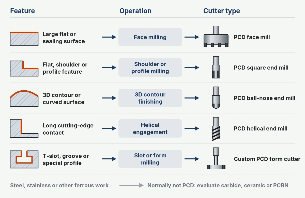
Choose the PCD Milling Cutter Type
Pick the cutter type from the feature and the toolpath.
| Milling task | Cutter type to evaluate | Main selection variables |
|---|---|---|
| Large flat or sealing surface | PCD face milling cutter | Diameter, pitch, effective teeth, insert height, axial runout, wiper design |
| Flat, shoulder, or profile feature | PCD square end mill | Cutting diameter, flute length, corner form, reach, chip space |
| 3D contour or curved surface | PCD ball-nose end mill | Ball radius, effective cutting zone, tool-axis angle, programmed step-over |
| Long cutting edge or helical engagement | PCD helical end mill | Edge continuity, helix construction, load distribution, evacuation path |
| T-slot, groove, or special profile | Custom PCD form cutter | Neck clearance, profile tolerance, interference, chip return path |
| Wide, repeat-production finishing | Indexable PCD face milling cutter or approved brazed/monoblock concept | Body rigidity, adjustment method, service route, spindle interface |
The table identifies a starting family. Final construction must be reviewed against cutter diameter, cutting length, collision risk, serviceability, and the machine interface.
Match Cutter Geometry to the Application
Cutter diameter and effective cutting length
Diameter affects spindle speed, engagement, reach, rigidity, and the number of passes. Effective cutting length affects overhang and deflection. Select the shortest practical reach that clears the feature and fixture. When a long reach is unavoidable, review tool body stiffness, holder condition, programmed engagement, and acceleration instead of compensating only with a lower feed.
Tooth count and chip space
More teeth do not automatically mean more productivity. Increasing tooth count changes:
- chip thickness at a given table feed;
- required spindle power and feed capability;
- flute or gullet space available for aluminum chips;
- the chance of chip recutting;
- sensitivity to tooth-height variation and runout.
The selected pitch must allow each active edge to carry a controlled load while leaving enough space for chips to exit the cut.
Rake, clearance, and edge preparation
These features influence cutting force, adhesion, edge strength, and response to interruption. A sharp edge may reduce cutting force and built-up material in a stable finishing cut, while an impact-prone feature may require a stronger edge concept. The final choice should be tied to the alloy, engagement, runout, and expected failure mode.
Square, corner-radius, and ball-nose forms
Choose the corner form from the feature geometry and toolpath:
- a square-end cutter produces a flat bottom and a nominally sharp axial corner where the drawing, cutter diameter, and edge construction permit it;
- a corner radius can redistribute edge load but changes the generated corner;
- a ball nose is used for 3D contours, but effective cutting speed varies across the ball;
- a form cutter can combine surfaces when the geometry, chip path, and inspection method are compatible.
Wipers and adjustable face mills
A wiper or adjustable cutting system may be considered for wide finishing passes and sealing surfaces. Its value depends on tooth-height control, axial runout, machine condition, feed, and the specified surface. Do not assume that adding a wiper will correct spindle error, weak fixturing, or unstable insert seating. See the indexable PCD face milling cutter as a product-family reference, then confirm whether an adjustable, brazed, or monoblock construction fits the application.
Material-Specific Selection Considerations
Wrought aluminum
The main concerns often include adhesion, built-up material, burr formation, chip evacuation, and the visual consistency of the machined surface. Review edge sharpness, lubricant delivery, chip thickness, flute space, and the risk of rubbing. For low volumes, compare PCD economics with a sharp aluminum-geometry carbide cutter before changing the whole process.
Cast and high-silicon aluminum
Hard silicon particles can create abrasive wear, while casting skin, inclusions, porosity, and interrupted entry can add impact. Record the alloy and silicon content, identify whether wear is uniform or localized, and define tool life by accepted output and a measurable change criterion. Do not transfer a parameter from one cast alloy to another without review.
Aluminum-SiC composites
Particle fraction, particle size, distribution, matrix condition, and edge engagement can change both surface formation and tool wear. Research on these composites reports application-specific combinations of abrasive wear, chipping, particle pull-out, pits, and subsurface damage (Wang et al., 2015; review of SiCp/Al machining research). A trial should therefore inspect both the cutting edge and the machined surface; surface roughness alone may not describe subsurface integrity.
Copper and brass
Copper and brass should not be treated as one material. Confirm the exact grade, hardness, chip behavior, surface requirement, and presence of interrupted features. Adhesion, burr formation, edge loading, and chip evacuation can differ between grades.
Materials outside the normal PCD window
PCD is not normally the first choice for conventional steel and stainless-steel production. At cutting temperature, carbon in the diamond reacts with iron, and the resulting chemical wear and graphitization are why PCD is not recommended for ferrous machining. Conventional ferrous applications generally require evaluation of carbide, ceramic, or PCBN according to the operation and hardness.
The same boundary applies to nominally aluminum parts that contain an unconfirmed steel sleeve, insert, fastener, or ferrous layer. Do not allow the PCD edge to enter that material stack until the insert material, contact path, temperature, and approved tool strategy have been reviewed. Any exception must be validated for the exact process rather than presented as a general capability.
How to Establish Speeds and Feeds
No single speed-and-feed table covers “PCD milling aluminum.” Published tool-supplier data separates cutting recommendations by material group, PCD grade, cutter construction, diameter, tooth count, engagement, and cooling condition rather than treating aluminum as one setting. The starting point depends on the material, cutter, engagement, machine, holder, coolant, and objective. XRZ's high-speed PCD machining for aluminum covers the aluminum application route; values for a given project still need engineering approval.
Collect these inputs before calculating a trial condition:
- material grade and condition;
- cutter diameter, construction, and effective teeth;
- roughing or finishing objective;
- axial and radial engagement;
- programmed toolpath and interruption;
- spindle speed, power, and feed limits;
- holder, overhang, and measured runout;
- coolant or lubrication strategy;
- current process data and failure mode;
- inspection and tool-change criteria.
Basic milling calculations
Cutting speed:
Vc = π × D × n / 1000
Table feed:
Vf = fz × z × n
Where:
- Vc = cutting speed in m/min;
- D = cutter diameter in mm;
- n = spindle speed in rpm;
- Vf = table feed in mm/min;
- fz = feed per tooth in mm/tooth;
- z = number of effective cutting teeth.
These formulas calculate relationships; they do not select a safe production value. Mark every proposed parameter as a supplier reference, engineering starting point, XRZ-validated condition, or customer production result. Keep the source and application boundary with the number.
Use a controlled trial sequence
- Inspect the spindle, holder, assembly, fixture, coolant route, and programmed engagement.
- Establish a conservative engineering starting point from the approved cutter design and material data.
- Define the stop limits for wear, edge damage, dimension, burr, and surface condition.
- Run a controlled sample and inspect both the part and the edge.
- Change one major variable at a time.
- Record the approved operating window, not only the best individual result.
- Freeze the tool revision and process conditions used for production approval.
Diagnose Common Milling Problems in the Right Order
| Observed problem | Check first | Do not assume |
|---|---|---|
| Built-up edge (BUE) or adhered workpiece material | Alloy, lubrication, chip thickness, edge condition, temperature | That the PCD grade is the only cause |
| Chatter marks | Assembled runout, overhang, holder, fixture, engagement, tooth pitch | That changing spindle speed alone will solve it |
| Poor or changing surface finish | Edge wear, axial runout, chip recutting, toolpath, material variation | That a new cutter automatically fixes the process |
| Burr formation | Edge wear, cutting direction, support, exit condition, chip load | That more feed is always the correction |
| Edge chipping | Interruption, impact, runout, edge preparation, entry path | That all chipping is a tool-manufacturing defect |
| Uneven face-milling marks | Tooth height, cutter-body runout, spindle condition, insert seating, pass overlap | That one roughness value explains the full surface |
| Short, inconsistent tool life | Material batch, runout, interruption, coolant, handling, wear criterion | That average tool life alone shows process control |
If the problem appears immediately after setup, inspect assembly and geometry first. If it develops gradually, compare the wear pattern and part-inspection trend. If it begins after a material, fixture, program, coolant, or tool-revision change, isolate that change before broad parameter adjustment.
Verify the Cutter in Production
A PCD milling trial should answer four questions:
- Does the cutter produce conforming parts at the proposed starting condition?
- Which edge-wear or damage pattern develops, and where?
- How does part quality change as the edge approaches the tool-change limit?
- Does the accepted-part economics justify the cutter and service route?
The validation record should include:
- tool drawing and revision;
- PCD construction or grade reference approved for the project;
- workpiece alloy and condition;
- machine, holder, overhang, and runout;
- coolant or lubrication method;
- program and engagement notes;
- speed, feed, axial depth, and radial width;
- inspection method and sampling interval;
- edge images at defined checkpoints;
- accepted parts, rejected parts, change reason, and reconditioning status.
Do not generalize a successful trial to another alloy, cutter diameter, feature, or machine without reviewing the changed variables.
PCD Milling Cutter RFQ Checklist
Send the following information for an engineering review:
- component drawing and revision;
- exact material grade, temper, silicon content, or reinforcement data;
- feature geometry and access limits;
- roughing, semi-finishing, or finishing task;
- required flatness, profile, dimension, surface, and burr criteria;
- current tool and current failure mode;
- machine model, spindle interface, speed/power limits, and holder;
- measured runout and required overhang;
- coolant, MQL, or dry-machining arrangement;
- cutting data and engagement from the current process;
- annual volume, batch size, and target tool-change method;
- inspection plan and sample-validation requirement;
- photos of the current wear pattern and machined surface, when available.
This information allows the supplier to decide whether a standard cutter family, a custom PCD geometry, or a stabilized carbide process is the appropriate next step.
Frequently Asked Questions
Is PCD always better than carbide for milling aluminum?
No. PCD is worth evaluating when abrasive wear, tool changes, or surface variation create enough production cost to justify it. Solid carbide may be more economical for prototypes, small batches, unstable cuts, or frequently changing work.
Is PCD suitable for high-silicon aluminum?
It is a common candidate because silicon can accelerate abrasive wear, but the alloy, silicon content, casting condition, cutter geometry, interruption, and production target must still be reviewed. Approval should follow a controlled trial.
Can one PCD cutter mill wrought aluminum, cast aluminum, copper, and brass?
Do not assume so. These materials differ in adhesion, abrasion, chip formation, burr behavior, and required edge geometry. Confirm the exact grade and operation before approving one design across materials.
Can PCD be used to mill steel?
PCD is normally not selected for conventional steel or stainless-steel milling because chemical wear can accelerate under cutting heat. Carbide, ceramic, or PCBN is generally evaluated instead, depending on the operation and hardness.
What determines tool life in PCD milling?
Tool life depends on the material and inclusions, cutter design, edge preparation, engagement, runout, machine and fixture condition, coolant or lubrication, chip evacuation, handling, and the defined change criterion. Report tool life as accepted parts or removed volume under documented conditions.
Prepare the Application Before Requesting a Cutter
Asking for a “long-life PCD end mill” gives the review nothing to work with. Define the material, feature, current process, observed wear, part-acceptance limits, and economic baseline. With those inputs, XRZ can review whether a PCD cutter concept fits the application, which cutter family should be evaluated, and what must be proven during sample validation.
When the drawing and process data are ready, submit a PCD milling application for review.