
Quick answer
Release a thread-milling program only after you confirm tool, thread, and machine inputs; build and verify the entry and helical path; set RPM and the plant feed convention; define passes and compensation at framework level; check the CAM file and posted code; then clear simulation and first-part gates. This page is a machine-agnostic verification checklist and a door to controller-specific guides when those pages are live. It is not a feed calculator, not a speeds-and-feeds deep dive alone, not a cutter-compensation essay, and not a blind-hole depth guide.
CAM and process engineers often paste a remembered milling feed into a helical cycle, skip an input field, or release a post without a traveler checklist. This Knowledge page owns the order of checks that keep those mistakes off the first article. Start with the thread milling guide for cluster navigation and the thread mill selection guide when the tool family is still open. Geometry and callout siblings already live: single-form vs multi-form thread mills, metric and UN thread mill callouts, and thread mill diameter vs hole clearance. Product geometry and inquiry live on the thread mill product page. Aluminum mill-versus-tap tradeoffs stay on the sibling thread milling vs tapping aluminum guide when you need that contrast.
Jump: Confirm inputs · Entry and helical path · RPM and feed convention · Passes and compensation · CAM and posted program · Release gates · Confirm · FAQ · Sources
Confirm tool, thread and machine inputs
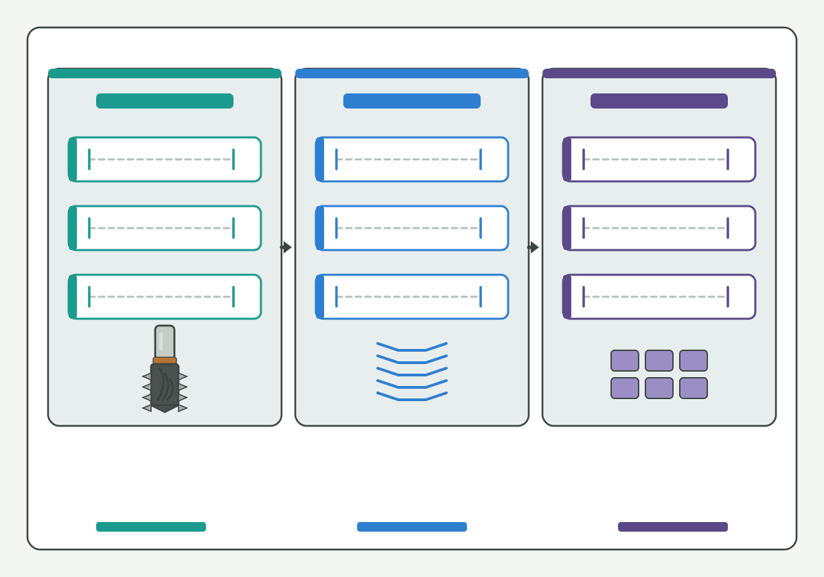
Illustration schematic: tool drawing, thread callout, and machine capability slots on one traveler - not a catalog claim or ranked photo.
Write three input stacks on the traveler before you open a CAM operation:
- Tool drawing fields: cutting OD, shank, cutting length, neck, tooth form or pitch match note, coating or substrate note if stated, and measured stick-out when known.
- Thread callout: system, nominal, pitch or TPI, form, tolerance class, and required engagement as written on the controlled drawing (leave blank fields blank).
- Machine capability: spindle speed range, axis travel and interpolation limits that matter for the helix, coolant delivery mode, and holder interface class.
If any stack is incomplete, stop and mark the missing field [NEEDS VERIFICATION]. Do not invent a controller parameter or a catalog OD from a nickname. Soft note (guide forthcoming, no empty hard link): a dedicated feed calculator page will own interactive unit checks later; keep only the input definitions on this traveler for now.
Public threading literacy such as this threading knowledge overview and this thread milling process overview helps name helical generation without publishing an HENTRY parameter table. Units literacy such as this units and measurement guidance and this public metrology laboratory entry support honest unit fields. Toolholding literacy such as this tool-holder interface overview and this toolholding tips overview helps name runout and projection checks that still change usable stick-out.
Start here: if the tool drawing, the print callout, and the machine capability card disagree, do not build the helical path yet. Soft note: controller-specific CAM or control setup pages will sit behind this checklist when published; until those URLs are live, keep plant controller handbook revision on the traveler and do not hang an empty hard link.
Build and verify the entry and helical path
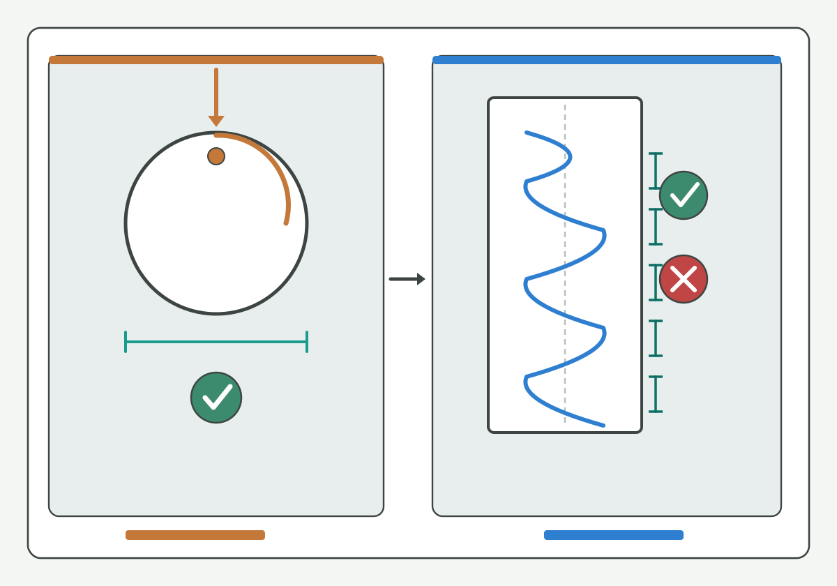
Illustration schematic: entry approach, helical orbit, and retract verification - unique gain as a path checklist, not a ranked catalog or life claim.
Build the path in three named segments, then verify each against the drawing and the fixture:
- Entry / approach: how the tool reaches the start plane without colliding with the entry, counterbore, or boss.
- Helical orbit: centre-path radius, pitch advance per revolution, and direction notes as your plant defines them (leave engagement style as a traveler note, not as a feed claim).
- Retract: how the tool leaves the feature without dragging the non-cutting body through a step or thin wall.
Hard-link geometry siblings when the path question is really a clearance question: use thread mill diameter vs hole clearance for entry, envelope, and centre-path gates, and use single-form vs multi-form thread mills when tooth count changes how many orbits you need. Callout literacy belongs on metric and UN thread mill callouts when the print system is still open.
Milling process literacy such as this milling process overview supports orbit language. Thread-milling product literacy such as this thread milling resource overview, this thread milling cutter overview, and this thread milling article overview helps name family language without migrating brand clearance tables into this page. Soft note (guide forthcoming, no empty hard link): internal versus external direction essays and blind-hole full-thread depth detail will sit on dedicated pages when published; keep only path-verification fields here.
Hypothetical teaching note (not a verified HC customer case): a traveler that lists a helical pitch but leaves entry plane blank is not ready for simulation. Mark the entry field [NEEDS VERIFICATION] and stop before posting.
Calculate RPM and the required feed convention
This section owns the framework only: which symbols and diameters your plant freezes before numbers enter the program. It does not own a full speeds-and-feeds deep dive or an interactive calculator.
- Approved cutting speed or starting band: take from the approved tool/material card or mark teaching inputs as hypothetical / [NEEDS VERIFICATION].
- Spindle RPM: convert from cutting speed and the diameter your plant defines for that conversion (cutting OD versus another reference). Write the diameter definition on the traveler so two programmers do not disagree later.
- Feed convention: state whether the posted feed is centre-path feed, tooth feed at the periphery, or another plant-standard convention. Do not paste a flat end-mill feed into a helical cycle without naming the convention.
- Effective circumferential edges: record how many edges your plant counts for the feed equation; do not invent a flute count from a nickname.
Soft note (guide forthcoming, no empty hard link): a dedicated speeds-and-feeds Knowledge page will own worked conversions from tool data to programmed feed; a feed calculator page will own interactive unit checks. Until those URLs are live, keep formula notes and unit checks on this traveler and do not hang empty hard links.
Machining data literacy such as this machining data literacy portal, research literacy such as this peer-reviewed machining research journal overview and this machining process and tool development research overview, and tapping literacy such as this tapping knowledge overview (contrast only) keep method language public without inventing HENTRY SFM tables.
Hypothetical teaching note (not a verified HC customer case): if two programmers share the same cutting-speed number but one uses cutting OD and the other uses a smaller reference diameter for RPM, the posted spindle speed will disagree even when both claim the same card. Freeze the diameter definition before you calculate.
Define passes and compensation
Define passes and compensation at framework level on this checklist. Do not turn this page into a full pass-strategy essay or a cutter-compensation deep dive.
- Pass count and radial stock plan: roughing versus finishing orbits, spring passes if your plant uses them, and which pass owns the final profile.
- Compensation mode: whether the CAM or control applies radius or diameter offset, and which wear or geometry register your plant expects (leave register numbers blank if the handbook is not verified).
- Wear / geometry update rule: who may edit offsets after first article, and how the traveler records the change.
Soft note (guide forthcoming, no empty hard link): a dedicated pass-strategy Knowledge page and a dedicated cutter-compensation Knowledge page will own those essays when published. Keep only the framework fields and stop conditions here.
Threading article literacy such as this threading article overview, tool-family literacy such as this threading tools overview and this thread milling tools overview, and manufacturer portal literacy such as this threading manufacturer portal stay neutral discovery aids. Geometry-inspection literacy such as this tool geometry inspection equipment overview helps name how shops confirm OD and profile before offsets are trusted.
Check the CAM and posted program
Before release, walk a CAM and post checklist that does not invent unverified G-code claims:
| Check | What you write | If missing |
|---|---|---|
| CAM version / file revision | Version string and part file revision on the traveler | Stop; do not post from an unnamed file |
| Workplane / WCS | Named plane and origin rule for the helix | Mark [NEEDS VERIFICATION] |
| Tool number and length offset | Matches the measured stick-out stack | Do not guess from a nickname |
| Compensation mode in CAM vs control | Radius / diameter / wear register note | Soft note: compensation essay forthcoming |
| Feed and RPM units | Match the plant feed convention frozen above | Do not mix centre-path and periphery feeds silently |
| Posted helical moves | Entry, orbit, retract present as planned | Reject the post; rebuild path |
| Coolant and spindle codes | Match machine capability card | Stop before simulation |
| Program number / comment block | Part, revision, and checklist owner | Do not invent a customer program ID |
CAM documentation literacy such as this CAM support and documentation overview and NC simulation literacy such as this NC simulation verification overview support naming verification steps without claiming an HENTRY-certified post processor. Soft note (guide forthcoming, no empty hard link): controller-specific CAM or control check pages will own screen-level checks when live; keep plant handbook revision here until then.
Standards literacy such as this codes and standards portal, this national standards overview, and this international metrology portal support naming systems and units without publishing an HENTRY class matrix.
Release only after simulation and first-part checks
Close the programming task only after release gates pass on the traveler:
- Simulation / collision review: entry, helical orbit, and retract clear the model and fixture as far as your plant verifies; mark Soft HOLD items that still need the real controller handbook.
- First-part plan: which feature is cut first, who watches the cut, and what stop conditions abort the cycle (noise, load, visible collision risk, coolant loss).
- Acceptance: gauge or CMM rule for the thread, and who signs the first-article row.
- Change control: how feed, RPM, or offset edits after first article are written back to the traveler.
Procurement and traveler fields may stay blank; blank is better than invented digits or invented program numbers. Soft note (guide forthcoming, no empty hard link): blind-hole full-thread depth and bottom clearance detail will sit on a dedicated page when published; do not substitute a remembered depth rule here.
Threading resource literacy such as this threading resources hub remains a discovery aid only. When tool and validation inputs are written - even with blank fields - move to product review instead of another nickname search.
How HENTRY supports the programming checklist
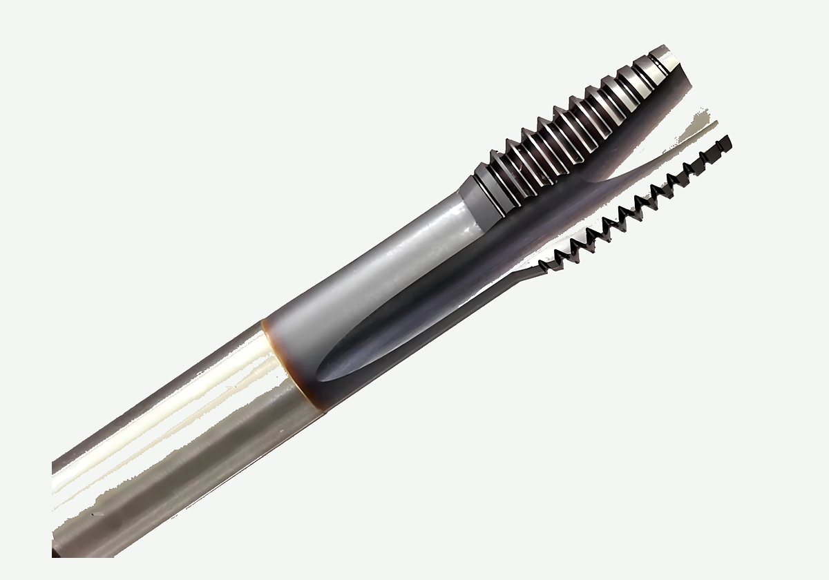
Product rematte of tip, flutes, and shank on a thread-mill body - not a ranked catalog or life claim.
HENTRY manufactures drawing-based cutting tools, including solid carbide thread mills. When tool drawing fields, thread callout, machine capability, path verification, feed convention, and release gates are written - even with blank Soft HOLD items - you can move from this Knowledge checklist to a product review instead of pasting an unverified milling feed into a helical cycle.
Next action: Review the matched tool and validation inputs. When the controlled drawing and traveler fields are ready to send, open the custom cutting tool RFQ. Quotation turnaround after complete drawings is typically 1-2 working days for engineering review, not a promise of unvalidated cutting data or program numbers.
Thread milling programming FAQ
Can I paste a flat end-mill feed into a thread-milling cycle?
No. Freeze the plant feed convention first (centre-path versus periphery tooth feed, or another named rule). A flat milling feed without that convention is not a verified helical input. Mark missing convention fields for verification and stop before posting.
What if the controller handbook is missing?
Stop before you invent register numbers, G-code claims, or spindle limits. Write the missing handbook revision as a Soft HOLD item, keep the machine-agnostic checklist fields you can verify, and wait for the plant handbook or a controller-specific guide when that page is live.
What should I verify first on the helical path?
Verify entry approach, helical orbit (centre-path radius and pitch advance), and retract against the drawing and fixture. Clear diameter and envelope gates on the related clearance guide when the question is geometry, not programming order.
When should I open a controller-specific programming check page?
Open controller-specific CAM or control check pages only when they are live and your plant needs screen-level checks. Until then, keep this machine-agnostic checklist, record the handbook revision, and do not hang empty hard links.
Does this page finish compensation and pass strategy?
No. This page only freezes framework fields for passes and compensation. Dedicated pass-strategy and cutter-compensation Knowledge pages will own those essays when published. Soft-note those topics here instead of empty hard links.
Sources and related guides
Authoritative literacy (neutral anchors; discovery only; not HENTRY catalog limits or life claims). Link check Asia/Shanghai 2026-10-31:
- threading knowledge overview
- thread milling process overview
- milling process overview
- tapping knowledge overview
- thread milling resource overview
- threading resources hub
- threading manufacturer portal
- thread milling cutter overview
- thread milling article overview
- threading article overview
- threading tools overview
- thread milling tools overview
- tool-holder interface overview
- toolholding tips overview
- units and measurement guidance
- public metrology laboratory entry
- codes and standards portal
- national standards overview
- international metrology portal
- peer-reviewed machining research journal overview
- machining process and tool development research overview
- machining data literacy portal
- tool geometry inspection equipment overview
- NC simulation verification overview
- CAM support and documentation overview
Related live pages: thread milling guide · thread mill selection guide · thread milling vs tapping aluminum · single-form vs multi-form thread mills · metric and UN thread mill callouts · thread mill diameter vs hole clearance · thread mill product page. Soft note only (no empty hard links): feed calculator, speeds-and-feeds deep dive, controller-specific CAM or control checks, cutter compensation, pass strategy, direction (internal/external), and blind-hole depth Knowledge pages are forthcoming.
When the matched tool and validation inputs are ready, Review the matched tool and validation inputs.