
Quick answer
In a blind hole, align full thread depth on the drawing with actual or specified drill depth, identify the real bottom geometry, then check the end-tooth envelope and bottom clearance before you accept a usable thread. Measure usable thread depth on the part after the cut. This page owns blind-hole full thread depth and bottom clearance. It does not own entry or profile clearance essays, and it does not own a machine-agnostic programming checklist. There is no universal depth percentage that replaces those checks.
Process, CAM, and drawing-review engineers often program a blind-hole thread mill from a remembered depth or a nickname, then find the end tooth hits the floor, chips pack at the bottom, or the gauge fails short of full thread depth. This Knowledge page owns how to read full thread depth against drill depth, identify flat, conical, or residual bottoms, check end-tooth and neck envelopes at the floor, accept or reject usable thread on paper and on the part, and record the decision before product inquiry. Start with the thread milling guide for cluster navigation, then use the thread mill selection guide when the candidate family is still open. Entry diameter and centre-path clearance stay on the thread mill diameter vs hole clearance guide. Geometry contrasts between single-form and multi-form tools stay on the single-form vs multi-form thread mills guide. Callout reading stays on the metric and UN thread mill callouts guide. Aluminum mill-versus-tap tradeoffs, including pre-hole and depth language on that page, stay on the sibling thread milling vs tapping aluminum guide. Product geometry and inquiry live on the thread mill product page.
Jump: Full thread vs drill depth · Bottom geometry · End-tooth vs bottom clearance · Accept or reject · Record decision · Confirm · FAQ · Sources
Read full thread depth and drill depth
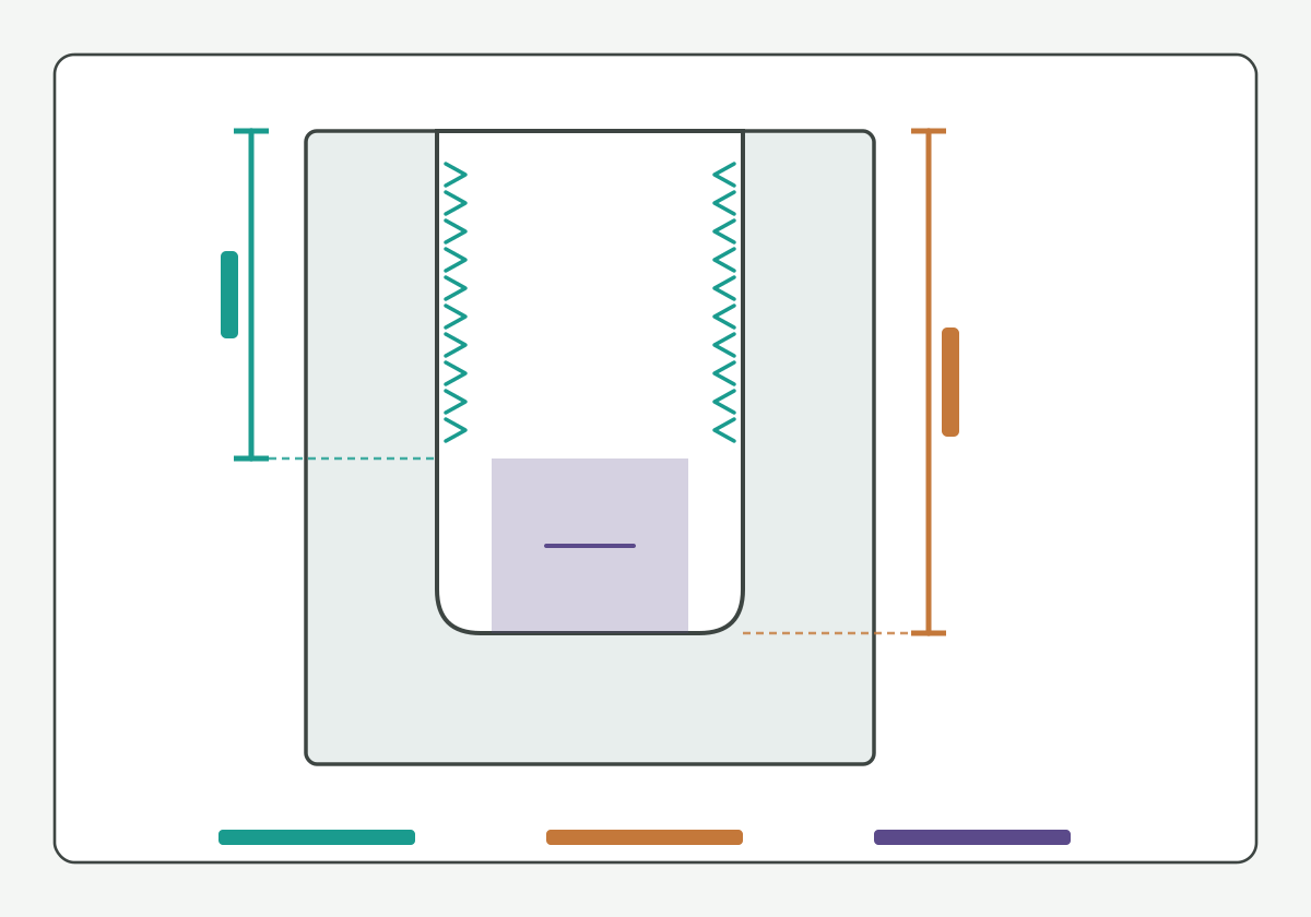
Illustration schematic: full thread depth versus drill depth on a blind-hole section with blank ticks - teaching layout only; not a catalog claim or acceptance photo.
Write two separate depths on the traveler before you open a tool or a Z program:
- Full thread depth: the axial length of complete usable thread required by the drawing (sometimes named "full form" or "usable thread"); leave blank if the print only shows a total hole depth.
- Drill / pre-hole depth: the actual or specified drilled depth that creates the blind cavity, including any point or residual floor your plant still leaves.
Full thread depth is not the same as total hole depth, and it is not the same as programmed Z travel. If the print and the measured blank disagree, mark both fields [NEEDS VERIFICATION] and Soft HOLD. Do not invent a "standard" leftover percentage between drill depth and full thread. Public threading literacy such as this threading knowledge overview and this thread milling process overview helps name helical generation without publishing an HENTRY depth table. Screw-thread handbook literacy such as this screw-thread handbook reference and units literacy such as this units and measurement guidance support naming systems and units honestly.
Start here: if either full thread depth or drill depth is unknown, do not accept a usable-thread claim. Use the live thread milling programming guide for the machine-agnostic verification checklist. Soft note (guide forthcoming, no empty hard link): a speeds-and-feeds conversion page will sit on a dedicated Knowledge URL when published; keep only the depth and floor fields on this traveler for now.
Identify the actual bottom geometry
After the two depths are written, name the real bottom you will meet:
- Flat floor: a bottom that was spot-faced, flat-bottom drilled, or otherwise left nearly planar;
- Conical / drill-point floor: a residual cone or point left by the pre-hole drill;
- Unpierced residual stock: material still between the floor and a far face, thin wall, or pocket;
- Interrupted floor: cross holes, slots, or exits that break the floor plane.
Sketch the floor on the section view. A conical residual floor shortens the axial room available for complete thread form even when total drill depth looks generous on a nickname. Cross holes and thin floors force a stop-field on the traveler before you accept "full thread" language. Soft note (guide forthcoming, no empty hard link): deep reach and neck-length essays will sit on a dedicated reach page when published; this page only names the floor geometry that changes bottom clearance.
Milling process literacy such as this milling process overview and tapping literacy such as this tapping knowledge overview are contrast aids: a tap bottoming story does not replace blind-hole thread-mill floor checks. Toolholding literacy such as this tool-holder interface overview and this toolholding tips overview helps name projection stacks that still move the end tooth into the floor.
Hypothetical teaching note (not a verified HC customer case): a drawing may call full thread to a depth that fits only if the pre-hole is flat-bottomed, while the blank still carries a drill point. Label that mismatch as a floor-geometry Soft HOLD; do not close it with a remembered leftover percentage.
Check end-tooth envelope versus bottom clearance
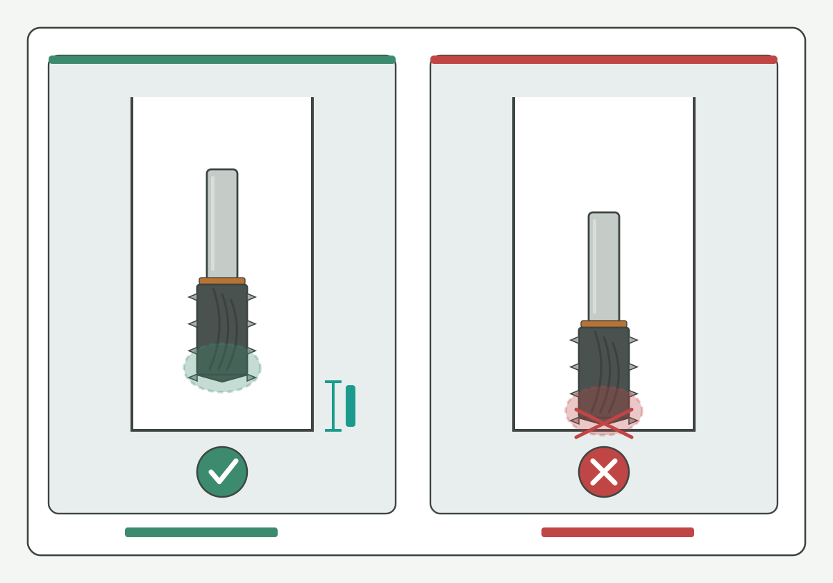
Illustration schematic: end-tooth envelope versus bottom clearance with clear and collide glyphs - unique gain for blind-hole floor checks; not a percentage rule, ranked catalog, or life claim.
At the floor, treat the end-tooth envelope and the bottom clearance as two stacks:
- End-tooth envelope: the axial and radial volume swept by the tip teeth (and any non-cutting tip geometry) while generating the last usable thread form;
- Neck / body behind the tip: the volume that can still hit a step, boss, or conical residual while the tip is near the floor;
- Bottom clearance: the free space between that envelope and the actual floor, including room for chips and for a controlled retract.
Write three fields when you have them: lowest programmed Z that still makes complete form, measured or specified floor Z, and clearance = floor minus envelope (leave blank if either input is missing). If clearance is blank or negative on paper, reject usable-thread acceptance before first article. Entry chip space and retract path matter here as traveler notes: chips packed at a blind floor are a clearance failure mode, not a reason to invent pressure or life claims. Entry OD and centre-path clearance during the orbit stay on the thread mill diameter vs hole clearance guide; this page stops at the floor envelope.
Thread-milling product literacy such as this thread milling resource overview, this thread milling cutter overview, and this thread milling article overview helps name family language without migrating brand bottom tables. Tool-family literacy such as this threading tools overview and this thread milling tools overview stays a neutral discovery aid. Geometry-inspection literacy such as this tool geometry inspection equipment overview helps name how shops confirm tip envelopes before the first article. Coolant path literacy such as this coolant concentration measurement method supports fluid-control language when chips pack at a blind floor, without inventing an HENTRY pressure guarantee.
Hypothetical teaching note (not a verified HC customer case): a candidate may clear entry OD on the clearance page yet still collide when the end tooth reaches a conical residual floor. Label that failure as an end-tooth / bottom-clearance reject on this traveler; do not hide it behind a depth nickname.
Accept or reject the usable thread
Close geometry only after an explicit accept / reject / hold on usable thread:
- Accept on paper: full thread depth and drill depth agree, floor geometry is named, end-tooth envelope clears the floor with retract and chip space noted;
- Reject: blank or negative bottom clearance, unpierced thin floor risk unmarked, cross-hole interruption ignored, or traveler cites only a remembered depth percentage;
- Hold: any critical field still [NEEDS VERIFICATION] (drawing vs blank, tip envelope vs catalog sketch, gauge method).
Conditional floor worksheet (fill with confirmed drawing or measured values; leave blank if unknown):
| Field | What you write | If missing |
|---|---|---|
| Full thread depth | Usable complete form required by the print | Stop; do not invent a leftover % |
| Drill / pre-hole depth | Actual or specified cavity depth | Mark [NEEDS VERIFICATION] |
| Bottom geometry | Flat / cone / residual / interrupted | Do not assume flat |
| End-tooth envelope | Tip volume at lowest usable form | Soft HOLD; do not guess from nickname |
| Bottom clearance | Floor minus envelope (plus chip/retract note) | Reject usable-thread claim |
| Cross hole / thin floor | Pass / fail / hold with section note | Stop before first article |
| Usable depth on part | Gauge / section / optical result | Do not close from program Z alone |
| Decision | Accept / reject / hold | Do not release the traveler |
Standards and metrology literacy such as this codes and standards portal, this national standards overview, this international standards catalogue entry, this public metrology laboratory entry, and this international metrology portal support naming systems and units without publishing an HENTRY depth matrix. Machining research literacy such as this peer-reviewed machining research journal overview, this machining process and tool development research overview, and this machining data literacy portal keep method language tied to public sources rather than to invented shop ratios. Substrate blank literacy such as this carbide rod blank portfolio overview and regrind literacy such as this regrind inspection and economic review overview support tool-body talk without life percentages. Threading article literacy such as this threading article overview stays discovery only.
Record the depth decision on the drawing
Close the page task only after the traveler records a depth decision next to the print revision:
- pass / fail / hold for full-thread vs drill depth, floor geometry, and end-tooth / bottom clearance;
- usable thread depth measured on the part (gauge, section, or optical) with method named;
- thread callout fields already verified;
- material family and blank condition;
- cross-hole / thin-floor notes;
- open soft items (reach depth, programming checklist, feed conversion) left blank rather than invented.
Procurement checklist fields may stay blank; blank is better than invented digits. Hard-link live: thread milling programming guide. Soft note (guides forthcoming, no empty hard links): speeds-and-feeds conversion, reach/neck clearance, and RFQ checklist Knowledge pages will sit on dedicated URLs when published. When the floor decision passes on paper and on the part, move to product review instead of another remembered depth paste.
How HENTRY supports the blind-hole depth decision
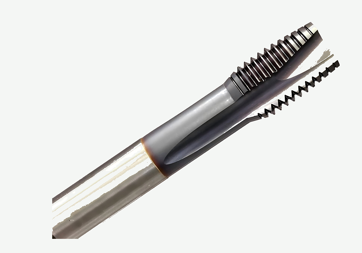
Product rematte of tip, flutes, and shank on a thread-mill body - not a ranked catalog, depth table, or life claim.
HENTRY manufactures drawing-based cutting tools, including solid carbide thread mills. When full thread depth, drill depth, floor geometry, and end-tooth / bottom clearance are written - even with blank Soft HOLD fields - you can move from this Knowledge slice to a product review instead of another remembered depth percentage. Public threading-resource literacy such as this threading resources hub remains a discovery aid only; do not migrate brand parameters into an HENTRY proposal.
Next action: Review the matched tool and validation inputs. When the controlled drawing and traveler fields are ready to send, open the custom cutting tool RFQ. Quotation turnaround after complete drawings is typically 1-2 working days for engineering review, not a promise of unvalidated cutting data.
Blind-hole thread milling depth FAQ
How much deeper should the drill be than full thread depth?
There is no universal leftover percentage that replaces drawing checks. Write full thread depth and drill depth as separate fields, name the real floor geometry, and confirm end-tooth clearance plus chip and retract space. If either depth is missing, mark verification and Soft HOLD instead of inventing a rule.
How do I tell that the end tooth is hitting the floor?
Compare the lowest Z that still makes complete usable form with the measured or specified floor, including conical residuals. Negative or blank clearance on paper, tip marks on the floor, packed chips with no retract path, or a gauge that fails short of full thread are reject signals. Do not close from program Z alone.
What should I watch with cross holes or thin floors?
Treat interrupted floors and unpierced thin residual stock as stop fields. Sketch the interruption, hold usable-thread acceptance until the section is named, and record pass, fail, or hold next to the print revision before first article.
How is this different from entry and profile clearance?
Entry and profile clearance ask whether the tool can pass the opening and orbit without wall collision. This page asks whether full thread depth fits the drilled cavity and whether the end-tooth envelope clears the blind floor. A candidate can pass entry checks and still fail at the floor.
Can I accept usable thread without a section or gauge record?
No for production close-out. Program Z is not proof of usable thread depth. Record a gauge, section, or optical result with method named, or keep the traveler on Soft HOLD.
Sources and related guides
Authoritative literacy (neutral anchors; discovery only; not HENTRY catalog limits or life claims). Link check Asia/Shanghai 2026-10-31:
- threading knowledge overview
- thread milling process overview
- milling process overview
- tapping knowledge overview
- thread milling resource overview
- thread milling cutter overview
- threading resources hub
- thread milling article overview
- threading article overview
- threading tools overview
- thread milling tools overview
- tool-holder interface overview
- toolholding tips overview
- coolant concentration measurement method
- tool geometry inspection equipment overview
- screw-thread handbook reference
- units and measurement guidance
- codes and standards portal
- national standards overview
- international standards catalogue entry
- public metrology laboratory entry
- international metrology portal
- peer-reviewed machining research journal overview
- machining process and tool development research overview
- machining data literacy portal
- regrind inspection and economic review overview
- carbide rod blank portfolio overview
Related live pages: thread milling guide · thread mill selection guide · single-form vs multi-form thread mills · metric and UN thread mill callouts · thread mill diameter vs hole clearance · thread milling vs tapping aluminum · thread mill product page. Also see the live thread milling programming guide. Soft note only (no empty hard links): speeds-and-feeds conversion, reach/neck clearance, and RFQ checklist Knowledge pages are forthcoming.
When the floor decision and traveler fields are ready, Review the matched tool and validation inputs.