
A tap shears off at the bottom of a blind hole, and the first reaction on the floor is to question the tap. We question the chip first. Before we discuss grade, coating or a different series, we establish where the chip was supposed to go and how much room it had to get there, because in blind-hole work that single input explains more breakage than tool selection does.
This page covers diagnosis only: broken taps, torn or smeared thread flanks, and threads that gauge oversize. We keep three neighbouring topics off it on purpose.
Chamfer and flute family choice sits on tap types for blind and through holes. The forming-versus-cutting decision sits on form tap vs cut tap. Pilot-hole arithmetic sits on the tap drill size chart and the size pages under it. Here we take the failure as given and work backwards to the input that produced it.
Jump: Three failure families · Diagnosis order · Chip evacuation · Pilot hole · Synchronization · Breakage vs wear · Walkthroughs · Symptom index · RFQ checklist · Confirm · FAQ
Quick answer
- Name the failure family before touching a parameter. Breakage, torn flanks and oversize have different first checks, and a correction aimed at the wrong family makes the other two worse.
- Check chip room before tool condition. In blind holes the pilot depth above the thread, the flute direction and the chip form decide whether the tap ever reaches full depth without packing.
- Confirm which pilot formula your tap needs. Cutting taps run D = TD − TP; forming taps run D = TD − TP/2. Applying the cutting formula to a forming tap raises torque sharply and is a routine cause of mid-hole breakage.
Three failure families, three different first checks
We start by naming which family the failure belongs to, because the three respond to opposite corrections. A tap that snapped is a strength event. A thread with torn or smeared flanks is a friction and chip event. A thread that gauges oversize is a geometry or synchronization event. Reading the part before reading the program is what stops us tuning the wrong variable for an hour.
The table below is the split we use on the bench. It is a decision aid, not a ranking: none of the three families is rarer than the others in our experience, and each one can produce a part that looks acceptable at the entry and fails at the gauge.
| Family | What we see on the part | What we check first | What we deliberately leave alone |
|---|---|---|---|
| Breakage | Tap fractured, often at a flute root or close to the shank; stub left in the hole; the surviving flutes show little wear | Chip room and pilot depth, then torque demand | Coating and grade |
| Torn or galled flanks | Flank material smeared or ripped away; crest often looks acceptable; the gauge binds on the flanks rather than the crest | Lubrication and synchronization, then work hardening | Thread tolerance class |
| Oversize or out of tolerance | Pitch diameter above limit; thread looks clean; the gauge enters further than it should | Tap wear and back taper, then spindle-feed match | Pilot size on its own |
So the next step is not a parameter change. It is a decision about which of these three you are actually looking at, and that decision is made with the part in hand and a gauge on the thread, not from the program listing.
Our diagnosis order, and why chip comes before tool
We run the same five checks in the same order on every tapping problem, and we do not skip ahead. The order is deliberate: each check can explain the failure by itself, so changing two inputs at once destroys the evidence and usually breaks the next tap as well.
Only step four concerns the tap itself. In our workflow the tap is the last suspect, not the first, and we say so to the shop even when the tap is what broke.
- Chip room. Does the chip have a path out and somewhere to sit? This is a question about flute direction, pilot depth beyond the thread, and whether the material produces coils or powder.
- Pilot size and depth. Was the pilot drilled with the formula that matches this tap type, and is it deep enough that the tap is not bottoming on compacted chip?
- Synchronization. Does spindle rotation match Z feed through the entry and the exit, or is the tap being pulled and compressed?
- Tool condition and geometry. Wear land width, back taper, edge chipping, and whether a regrind removed the back taper without anyone noticing.
- Measurement. What was actually measured, with which gauge, at which position, and against which limit. A thread reported as bad without this detail is not yet a finding.
Chip evacuation: the input that decides the other four
We treat chip evacuation as the primary variable rather than a housekeeping issue, because it changes what every later check means. A tap with perfect geometry and no room for the chip will break at a depth that looks random until you plot it against the reservoir.
In a through hole the chip leaves ahead of the tool. A spiral-point tap pushes it forward, a longer entry chamfer starts the cut gently, and the practical questions become exit support and exit burr rather than chip room.
In a blind hole the chip has to travel back up the flutes, which is why a spiral-flute tap pulls it backwards and why a straight-flute tap in a short-chipping material needs a retraction plan rather than a continuous cut.
The most common single error we are asked to look at is a forward-pushing tap in a blind hole. The chip arrives at the bottom with nowhere to go, compacts against the hole floor, and the tap is asked to cut through its own debris. Breakage then happens a few millimetres short of full depth, which reads like a depth or program fault rather than a chip fault.
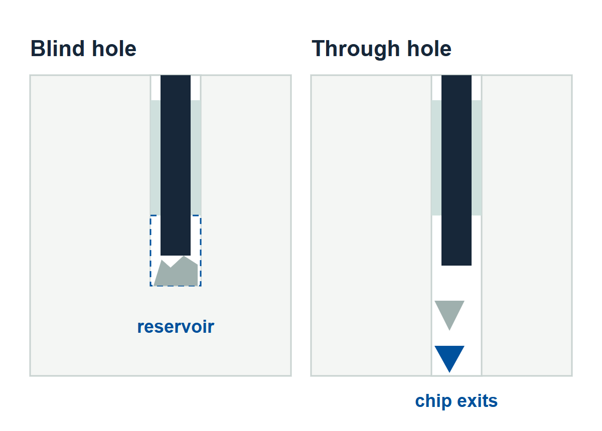
The signature we look for is a torque rise through the last few millimetres at otherwise constant depth, sometimes with audible squeal, and chips welded between flutes when the tap comes out. Breakage at the point where the reservoir runs out, rather than at a fixed depth across parts, is the strongest indicator that chip room is the driver.
We do not publish a universal reservoir figure. How much pilot depth you need above the usable thread depends on chip form, and chip form changes with material condition inside the same grade. We size it per job and confirm it on a first-off rather than quoting a multiplier that will be wrong on the next alloy.
Pilot hole: two formulas and the error that breaks taps
Pilot size is where a cutting tap and a forming tap stop being interchangeable. The two formulas differ by half a pitch, which is small enough to pass a visual check and large enough to change the torque demand substantially.
For a cutting tap the flanks remove material, so the pilot equals the nominal diameter minus the full pitch. For a forming tap the material is displaced rather than removed, so the pilot equals the nominal diameter minus half the pitch. Using the cutting-tap pilot for a forming tap leaves too little material to displace and is one of the most reliable ways to break a tap in the middle of a hole.
| Thread | Pitch TP | Cutting tap pilot, D = TD − TP | Forming tap pilot, D = TD − TP/2 |
|---|---|---|---|
| M6 × 1.0 | 1.00 mm | 5.00 mm | 5.50 mm |
| M8 × 1.25 | 1.25 mm | 6.75 mm | 7.38 mm |
| M10 × 1.5 | 1.50 mm | 8.50 mm | 9.25 mm |
| M12 × 1.75 | 1.75 mm | 10.25 mm | 11.13 mm |
| M16 × 2.0 | 2.00 mm | 14.00 mm | 15.00 mm |
| 1/4-20 UNC | 1.27 mm | 5.08 mm | 5.72 mm |
| 5/16-18 UNC | 1.41 mm | 6.53 mm | 7.23 mm |
These are nominal-geometry values at full thread height. If the print asks for a reduced thread height the pilot moves up, and that arithmetic belongs on the tap drill size chart and its size pages, such as 1/4-20, 5/16 and NPT. We keep the formula here and the numbers there so the two cannot drift apart.
Depth is the second half of the same check. A pilot cut to the same depth as the thread leaves no reservoir, so the tap reaches full form with the chip already packed against the floor. We specify pilot depth as usable thread depth plus chip room, and we write both numbers on the traveler rather than one.
Torn threads and oversize: synchronization before tool quality
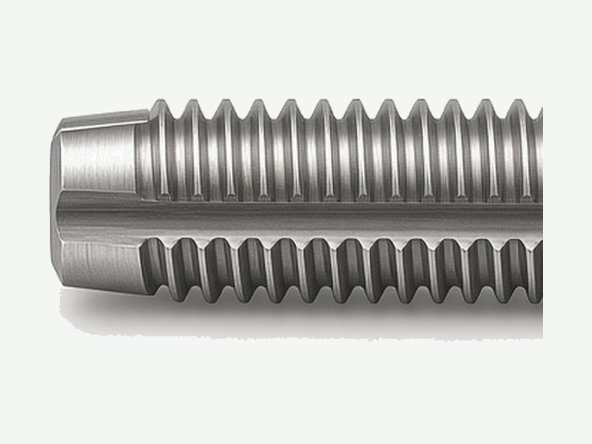
When the flanks are torn but the crest is intact, we stop looking at the tap and start looking at the machine. Tapping is a geared operation in principle: one revolution of the spindle must advance exactly one pitch. When that relationship slips, the tap is stretched or compressed along its axis, and the damage shows up on the flanks first.
Rigid tapping holds the relationship in the servo loop, which is precise once the tap is engaged but unforgiving during entry and exit, where acceleration has to match the pitch.
A floating holder absorbs the mismatch instead, at the cost of added length and reduced rigidity, which can convert a synchronization problem into a chip or chatter problem. Neither choice is universally right; the point is to know which one you are relying on.
The signature we use to separate synchronization from tool wear is depth dependence. Synchronization damage starts clean at the entry and degrades as the tap goes deeper, and a pitch measured across many threads drifts away from nominal. Tool wear tends to be more uniform, or localised where the cut is heaviest, and does not systematically worsen with depth.
We have no spindle-error measurements of our own to publish for specific machine models, so we do not attribute a failure to synchronization on our own authority. We test it instead: run a short rigid-tapped trial at reduced speed and compare flank condition against the original part. If the damage pattern does not move, synchronization was not the driver.
Breakage is a strength problem, wear is an abrasion problem
These two look similar in a scrap bin and are opposites in correction. Breakage is about whether the edge can survive the load it meets; wear is about how long the edge resists abrasion.
Increasing toughness to stop breakage usually costs wear resistance, and increasing wear resistance to extend life usually costs toughness, so a change made in the wrong direction will make the failure worse while appearing to follow good practice.
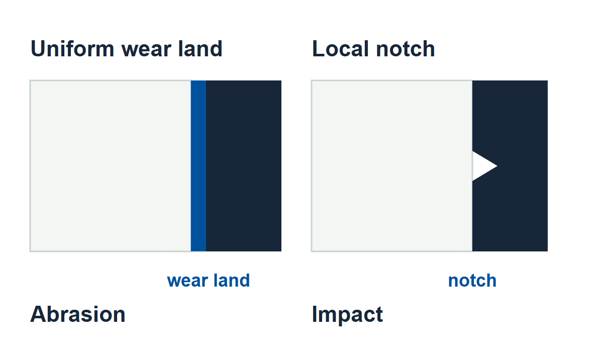
The distinction that matters most on the bench is between a chip notch and a wear land. A notch is local, sits at the depth line or where an interrupted cut re-enters, and indicates impact. A wear land is uniform along the cutting edge and indicates abrasion. The two call for different answers, and a notch treated as wear will keep growing until the edge fails.
| Observation | What it tells us | Correction direction | Correction we would avoid |
|---|---|---|---|
| Uniform wear land along the flank | Abrasion, normal progression toward end of life | Reduce cutting speed, or raise wear resistance | Edge strengthening, which costs clearance and raises torque |
| Local notch at the depth line | Impact or work-hardened layer meeting the edge | Change the entry condition, or remove the hardened layer by process order | Raising cutting speed to spread the load |
| Chipping along the whole edge | Load beyond edge strength, or unstable system | Reduce feed per revolution, shorten overhang, improve support | Higher wear resistance with a sharper, more fragile edge |
| Edge smeared with workpiece material | Pressure welding at the contact, usually a ductile material at the wrong speed | Change surface treatment or speed to leave the welding range | Treating it as wear and reducing speed further |
The practical consequence is that we do not change grade and geometry in the same trial. One variable at a time, with the failure family named in advance, is the only way the result tells you anything.
Three diagnosis walkthroughs (teaching scenarios, not measured cases)
The three walkthroughs below are the teaching scenarios we use to explain the check order to new staff. They are not records of specific customer jobs, they carry no life figures, and they are not offered as evidence that any particular tool will perform in a given way. Read them as a sequence of questions, not as a result.
M8 × 1.25, blind, 15 mm usable thread in 304 stainless, rigid tapping. The tap breaks at roughly 12 mm. Before changing anything we measure the pilot depth: it was drilled to 15 mm, matching the thread, which leaves no reservoir.
We also note the flutes are packed when the tap is extracted. Our first move is to drill the pilot deeper and add a retraction step, not to change the tap. We do not claim a life improvement from this, only that the breakage mechanism was addressed.
1/4-20 in AlSi10Mg die-cast, through hole, forming tap. The thread gauges oversize and the flanks look polished. The pilot was drilled to 5.08 mm, which is the cutting-tap value for that thread; the forming formula gives 5.72 mm. Too little material was available to displace, so the tap was forced and the formed thread lost its intended geometry. We correct the pilot and re-check the gauge result on a first-off.
M16 × 2 in GJV-450, blind, crossed by an interrupted cut. Chipping appears as a local notch rather than a wear land, and it sits where the interrupted cut re-enters.
We treat this as impact, not abrasion: the correction direction is the entry condition and system support, and raising cutting speed would be the wrong move. We state the direction only, because we have no wear data for this combination to put a number against.
Symptom index: what to check first, second and never first
This is the table we would hand someone who has a failed part and five minutes. It compresses the five-check order into a lookup, and the last column is the one we care about most, because most wasted shifts come from a plausible first move in the wrong direction.
| Symptom | First check | Second check | Not first |
|---|---|---|---|
| Tap broken at a depth short of full thread | Pilot depth and chip room | Flute direction against hole type | Grade or coating change |
| Tap broken immediately on entry | Pilot size against tap type formula | Entry chamfer and hole edge condition | Cutting speed |
| Tap broken on exit in a through hole | Exit support and burr condition | Feed match through the exit | Pilot depth |
| Flanks torn, crest intact | Lubrication at the contact | Spindle-feed synchronization | Thread tolerance class |
| Flanks torn and worsening with depth | Spindle-feed synchronization | Work hardening from a previous pass | Tap wear |
| Thread gauges oversize, form clean | Tap wear and back taper | Pilot size against the correct formula | Gauge calibration, unless the gauge is the only new variable |
| Thread tight on the gauge but within limit | Thread height percentage against the print | Pilot size | Tap replacement |
| Breakage only on the second or third part | Chip accumulation across the batch | Coolant or lubricant delivery over time | Tool life as a single number |
Procurement checklist: what to send with a tapping problem
When a tapping problem reaches us as a request, the useful submissions all contain the same seven items. When one is missing we ask for it before quoting anything, because a tool recommendation made without it is a guess dressed as advice.
- Workpiece material with condition and heat treatment, not just the grade family.
- Thread specification: nominal size, pitch, tolerance class, and whether the print asks for reduced thread height.
- Hole type and geometry: blind or through, usable thread depth, pilot depth, and any intersecting hole or interrupted cut.
- Pilot hole as actually drilled, with the drill diameter and the formula it was based on.
- Machine and holding: rigid tapping or floating holder, spindle speed limit, overhang.
- Cooling and lubrication: internal or external, and the lubricant type for stainless or aluminium work.
- Measurement and acceptance: gauge type, measuring position, and the limit that the part failed.
Leave commercial fields blank if you do not have them. A quoted price built on an invented quantity is worse than no price, because it anchors the conversation on the wrong number.
Confirm the specification with engineering support
We publish this page as a diagnostic method, not as a warranty. What it supports is the check order and the mechanism behind each step. What it does not authorise is a claim that a specific tap will reach a specific life in your material, because we do not have that data and will not invent it.
If you send the seven items above together with a photo of the failed tool and the failed thread, we will tell you which family we think the failure belongs to, which check we would run next, and where our knowledge stops.
That answer is free and it is honest about its limits. If the outcome is that you need a tool geometry we do not catalogue, the route is the custom cutting tool RFQ rather than a standard series substitution.
Tap Failure Diagnosis FAQ
Why do taps usually break in blind holes rather than through holes?
Because the chip has nowhere to go. In a through hole the chip exits ahead of the tap; in a blind hole it must travel back up the flutes, and if the pilot is not deeper than the thread there is no reservoir. The tap then cuts through compacted debris and the load rises until the edge or the shank fails.
How do I tell a torn thread from a worn tap?
Look at what the gauge binds on. Torn flanks bind on the flank with the crest intact, and the damage usually worsens with depth. A worn tap produces a thread that is dimensionally off across its whole length without the smeared, ripped flank appearance. The two need different first checks.
What is the correct pilot size for a forming tap?
Nominal diameter minus half the pitch, at full thread height. For M10 × 1.5 that is 9.25 mm, against 8.50 mm for a cutting tap of the same thread. Using the cutting-tap value on a forming tap is a common cause of mid-hole breakage.
Can a coating change fix tap breakage?
Rarely as a first move. Coating addresses friction and wear; breakage is usually a strength or load problem. A coating change made before the chip room and pilot checks have been run tends to move the failure rather than remove it, and it costs a trial to find that out.
Should I use a floating holder to stop torn threads?
It depends on which mismatch you have. A floating holder absorbs spindle-feed error but adds length and reduces rigidity, which can trade a synchronization problem for a chatter or chip problem. We test with a short rigid-tapped trial at reduced speed before changing the holder.
Why does the thread gauge oversize when the tap looks fine?
Check tap wear and back taper first, then the pilot against the correct formula. A forming tap run in a pilot drilled for a cutting tap loses formed geometry and can gauge oversize while the tool shows almost no visible wear. Do not adjust the tolerance class to compensate.
How much deeper than the thread should the pilot hole be?
Deep enough to hold the chip the operation will produce, which depends on thread size, material and chip form. We size it per job and confirm on a first-off rather than quoting a universal multiplier, because chip form changes inside the same material grade.
Does this page replace the tap drill size chart?
No. This page gives the two formulas and the diagnosis order. The tap drill size chart and its size pages carry the arithmetic for specific threads, including reduced thread height cases. Use both, and do not let one drift from the other.
Sources and related guides
External references support tapping and threading mechanism, thread tolerances and pilot-hole formulas, and dimensional metrology. We checked each link below on 4 November 2026 and list only pages that resolved. Manufacturer knowledge pages are cited for mechanism, not for product claims, and no third-party figure on this page is presented as our own measurement.
External: tapping knowledge · tap troubleshooting · threading formulas · NIST physical measurement laboratory · ASME codes and standards · DIN standards · BIPM · ASTM.
Related on-site: taps · spiral flute taps · spiral point taps · forming taps · straight flute taps · tap types for blind and through holes · form tap vs cut tap · tap drill size chart · internal and external threading · thread milling vs tapping aluminum · thread milling guide · custom cutting tool RFQ · resources.