
Search results for internal versus external threading often mix bolt-thread glossary pages, lathe-only tips, and tap or thread-mill catalogs on one screen. Process engineers then still lack a single place to decide which route fits the print: cut an external thread on a shaft, form or cut an internal thread in a hole, or mill either flank when access and tolerance demand it before they open an RFQ.
HC publishes this guide as a process-selection page for metal threading routes. You lock internal versus external features first, then turning / tapping / milling choice conditions, then tool reachability and accuracy windows, then standards and inspection literacy, then drawing and process inputs into RFQ. The page does not host SKU tables, absolute tolerance stock matrices, unverified life claims, or public prices. Tap series and buy-select geometry belong on the taps product page. Thread-mill series belong on the thread mill product page. Form versus cut tap method detail stays on the live form tap vs cut tap guide. Unified pilot-hole charts live on the tap drill size chart. Aluminum-focused mill-versus-tap path detail stays on its sibling thread milling vs tapping aluminum guide. Turning-insert selection for OD/ID finish work that is not a thread route stays on turning insert selection. Here you lock internal versus external threading methods before RFQ.
Jump: Decision flow · Features · Turning, tapping, milling · Reach and accuracy · Standards and inspection · Examples · Compare · RFQ checklist · Confirm · FAQ
Quick answer
- Name internal versus external first: internal threads live in a hole (nut-like); external threads live on a shaft or boss (bolt-like). Write which flank the print owns before you name a tool family.
- Pick the route by access, chip, and tolerance together: turning covers many OD/ID single-point cases; tapping covers many internal holes when pilot, torque, and exit allow; thread milling covers interrupted or large-pitch cases when spindle and program support helical interpolation. Do not treat any one route as automatic.
- Lock reach, gauge plan, and drawing blanks, then RFQ: confirm tool reach and holder clearance, name the thread standard and acceptance gauges, leave incomplete fields blank, then open custom cutting tool RFQ instead of inventing life or price digits.
Decision flow: flank → route → reach → standard → trial
Selection path (stop when a field is missing):
| Step | What you lock | If missing |
|---|---|---|
| 1 Flank | Internal (hole) vs external (shaft/boss) named on the traveler | Stop; do not jump to a tap or insert nickname |
| 2 Route family | Turning, tapping (form or cut), or thread milling as the primary path | Mark engineering-confirm; do not force habit |
| 3 Reach and accuracy | Tool length, holder clearance, pitch control, and finish window | Do not invent a permanent formula here |
| 4 Standard and inspection | Thread system, class/fit intent, gauge or optical check plan | Escalate before production |
| 5 Drawing inputs and RFQ | First-off notes + matched RFQ package | Open RFQ with incomplete fields if needed |
Read the steps in order. Shops often over-weight a single tool nickname or a brochure preference for "chip-free" language. That habit skips whether the print is even an internal flank, whether the spindle can hold pitch on a mill path, and whether the gauge plan matches the named class. Keep flank and route on the same traveler line so a label like tap does not hide a second process choice.
Public threading literacy such as this threading knowledge overview and this CNC threading and tapping overview helps name the conversation without inventing an HC stock list. Tapping literacy such as this tapping knowledge overview supports internal-hole routes only. Thread-milling literacy such as this thread milling process overview supports helical-interpolation naming. Standards literacy such as this codes and standards portal and this national standards overview supports thread-system naming. Metrology literacy such as this public metrology laboratory entry and this international metrology portal keeps units honest on the traveler. Manufacturing research portals such as this public manufacturing programs entry and this international standards catalogue entry support process-boundary language without claiming measured HC results.
Internal vs external thread features
An internal thread is cut or formed inside a prepared hole. The major diameter is the hole-side envelope; the minor diameter is the root of the female flank. Chip exit, bottom clearance, and gauge entry from the open end dominate the risk list. A external thread lives on a shaft, stud, or boss. The major diameter is the crest of the male flank; the minor diameter sits at the root. Tool approach from OD, shoulder clearance, and runout dominate instead.
Do not treat "metal threading" as one SKU family. The same nominal size on a print can mean an internal UNC hole for a fastener, an external metric shaft for a mating nut, or a tapered pipe flank that needs a different gauge story. Write flank, system, and pitch before you open a tap or insert catalog. Public fastener and thread nomenclature such as this thread basics overview helps name major/minor language without turning this page into a bolt encyclopedia.
Shop-floor language often collapses "thread it" into one verb. That shortcut hides whether the mating part is a male or female flank, whether the blank already has a pilot hole or a turned diameter, and whether the acceptance gauge enters from the same side as the tool. Write those three facts on the traveler before any catalog search. If the print only shows a callout bubble without a section view, stop and ask for a clearer drawing rather than guessing the flank from habit.
External threads on thin-wall tubes and internal threads in deep pockets also change lubrication and heat. A route that works on a short through hole can fail when the same nominal size sits at the bottom of a pocket with poor chip wash. Keep depth and open-end access on the same line as flank so the later route choice is not fighting a geometry surprise.
When the print mixes both flanks on one part, split the traveler: internal route and external route each get their own tool, lubricant, and acceptance line. Mixing them into one "thread job" line is a common source of wrong pilot holes and wrong insert grades later.
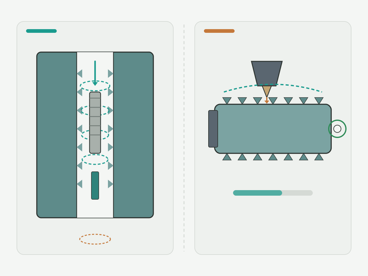
Schematic illustration - not a catalogue ranking or cutting-data table.
Turning, tapping, and thread milling: when each route fits
Single-point turning covers many external shafts and some internal bores when a boring bar or ID threading bar can reach. You control pitch with the lathe sync or CNC threading cycle. It is often the default for OD threads on turned parts when shoulder clearance and finish allow. It is not automatic for deep small-diameter internal holes where a tap or mill may be more practical.
Tapping covers many internal holes when the pilot hole, torque window, and exit or bottom clearance allow. Form (roll) taps displace ductile material; cutting taps remove chips. Method detail and ductility gates belong on the form tap vs cut tap guide; size-specific prep holes belong on the tap drill size chart and live size pages. Blind-hole flute and chamfer families are a separate Day8 page (soft-note until LIVE): do not treat taper / plug / bottoming nicknames as settled here.
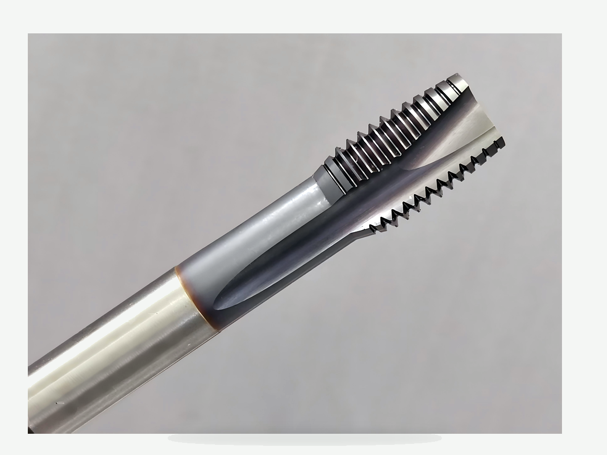
Thread milling covers both internal and external flanks when the machine can run helical interpolation, the cutter can reach, and the program owns pitch and pass strategy. It is often preferred for large pitches, thin walls that dislike tap torque, or interrupted features where a broken tap would scrap the part. Product geometry and series selection belong on the thread mill product page. Aluminum mill-versus-tap tradeoffs stay on the sibling Knowledge guide linked above. Milling is a support route on this page, not the pillar product pitch.
Sequence matters. Lock flank, then route family, then the sub-choice inside that family. For tapping, the sub-choice is form versus cut and then flute or lobe style. For milling, the sub-choice is cutter diameter, flute count, and pass strategy. For turning, the sub-choice is insert geometry and infeed style. Jumping straight to a SKU nickname skips the family gate and is how wrong pilots and wrong holders enter the job packet.
Hybrid jobs exist: rough an external flank on the lathe, then finish a critical length with a mill; or open a hole with a drill and finish the internal flank with a tap after a mill cleared an interrupted zone. Write each stage as its own line. Do not merge hybrids into a single brochure promise. When aluminum housings dominate the conversation, use the sibling mill-versus-tap guide for material-specific tradeoffs instead of copying steel habits into soft alloys.
Public cutting-data literacy such as this machining data literacy portal and toolholding literacy such as this toolholding technical tips overview help name spindle and holder constraints without inventing HC feeds tables. Treat every brochure "always mill" or "always tap" claim as conditional until access, material, and gauge plan are written down.
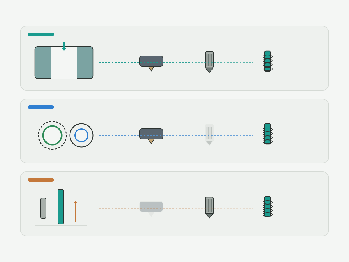
Schematic illustration - not a catalogue ranking or cutting-data table.
Tool reachability and accuracy windows
Reach is not only stick-out length. For internal work you also need chip exit or forming lobe clearance, coolant or lube path, and gauge entry after the cut. For external work you need shoulder and undercut clearance, steady or tailstock interference, and insert or mill approach angles that do not rub the finished crest.
Accuracy windows mix pitch control, flank finish, and class/fit intent. A lathe threading cycle, a rigid tap holder, and a thread-mill helix each fail differently when pitch drifts. Write the acceptance method before you chase a tighter nickname on the traveler. Optical or gauge checks must match the named system; do not paste a UNC class story onto a metric print without an engineering confirm.
Projection length interacts with chatter and pitch error. Longer stick-out can clear a shoulder and still lose pitch control if the holder is soft or the RPM window is wrong. Shorter stick-out can look rigid and still collide with a clamp. Sketch both collision and deflection before you freeze the tool length. If the only available tool in the crib fails either sketch, change the route or pull a custom RFQ rather than forcing a near-miss setup into production.
Accuracy also includes start timing. Lathe threading cycles need a consistent sync; rigid tapping needs a matching spindle and feed; thread milling needs a verified helix and pitch in the CAM post. A first-off that passes a go gauge once but fails after a tool change is a process signal, not a one-off mystery. Capture the holder ID and projection on the traveler so the next shift can repeat the window.
If the tool cannot physically reach the last engaged thread without colliding, stop and change the route or the blank design. Inventing a longer flute from a catalog nickname without a clearance sketch is a common scrap path. Keep holder, projection, and collision notes on the same line as the flank choice.
Thread systems, classes, and inspection
Name the thread system (for example UNC/UNF, metric coarse/fine, or a pipe taper family) before you name a tool. Class or fit intent (how loose or tight the mating pair should feel under the print) belongs next to the gauge plan. This page does not publish a full class table or measured HC stock matrix. Use public standards portals linked above as literacy, then confirm the print and the gauge maker's instructions before production.
Inspection is part of the route, not an afterthought. Ring or plug gauges, optical flank checks, and pitch micrometers each catch different errors. A first-off that "looks fine" without the named gauge is not a closed loop. If the print calls a special series or a coating that changes gauging feel, leave that field explicit on the RFQ instead of assuming a standard class.
Mixed prints are common in export jobs: a metric internal thread mating to a customer-supplied insert, or an inch external thread on a shaft that ships into a region that gauges differently. Translate the print into one system name on the traveler and attach the gauge maker instructions. If translation is unclear, leave the RFQ field blank and ask; do not invent a class letter to look complete.
Surface treatment after threading can change fit. Coatings, passivation, or paint on the flank may require a pre-coat thread class or a post-coat chase pass. Call that out as a process note. This page does not publish coating compensation tables; it only flags that acceptance must match the finished state the print actually ships.
Pipe tapers and straight fastener threads are different jobs. Do not copy a straight UNC tap-drill habit onto a tapered pipe callout. Size-specific NPT literacy lives on its own Knowledge page when you need that chart; this page only flags the system mismatch.
Worked examples (intent gates, not measured HC cases)
These examples are intent gates for traveler language. They are not measured customer results, life studies, or priced jobs.
| Situation | Flank | Route tendency | Stop if missing |
|---|---|---|---|
| Turned shaft with OD thread and open shoulder | External | Single-point turning often first | Shoulder clearance, pitch sync, finish/class intent |
| Through hole, ductile steel, standard fastener thread | Internal | Tapping often first; form vs cut still open | Pilot plan, torque window, exit clearance |
| Large internal pitch, thin wall, tap-breakage risk | Internal | Thread milling often reviewed | Helical program, cutter reach, wall deflection check |
| OD thread on a boss with interrupted flats | External | Milling or careful turning; not a blind tap story | Interrupt plan, approach angle, gauge access |
Use the examples as stop rules. If the situation matches a row but a Stop-if-missing cell is empty, do not promote the job to production feeds. Fill the cell, run a controlled first-off, or open RFQ with the blank visible. Invented completeness is worse than an honest incomplete packet.
If two routes both look plausible, write both on the engineering note and settle with a controlled first-off rather than inventing a universal ranking. Product pages for taps and thread mills take series selection after the route is locked.
Conditional compare: route families (not a ranking)
| Question | Turning tendency | Tapping tendency | Thread-milling tendency |
|---|---|---|---|
| Typical flank | External common; some ID with bar reach | Internal holes | Internal or external when helix is available |
| Chip / forming story | Single-point chip control | Cut chips or form displacement | Small chips from helical passes |
| Access risk | Shoulder and bar collision | Bottom pack / broken tap | Program and cutter length |
| When to pause | No sync or finish window | No pilot/torque/exit plan | No helical capability or reach |
Read across a row, not down a marketing column. A cell that says "often" is a tendency under stated conditions, not a warranty. When your material, depth, or machine list disagrees with a tendency, prefer the disagreeing evidence and document why. Sibling pages exist so this compare table stays short: form-versus-cut detail, pilot-hole numbers, and aluminum tradeoffs live elsewhere on purpose.
This table is conditional teaching language. It does not rank brands, invent feeds, or promise life. Re-check every cell against the print, material condition, and machine list before production.
Procurement checklist (RFQ inputs)
Before you open custom cutting tool RFQ, lock these fields or leave them explicitly blank:
- Flank: internal or external (and both if the part needs two routes)
- Thread system, nominal size, pitch, and class/fit intent from the print
- Material grade and condition; ductility notes if forming is under review
- Hole or OD geometry: through/blind, depth, shoulder, undercut, interruptions
- Machine and holder: lathe sync, rigid/tap holder, or helical interpolation capability
- Acceptance: gauge type, optical check, or other named method
- Quantity and timeline as known; leave unknown commercial fields blank (no invented price or life)
Browse other process guides from the resources hub when you need a sibling chart. Do not paste unfinished numbers into the RFQ to look complete.
Confirm the specification with engineering support
When the traveler still has open fields on flank, route, reach, or gauges, stop guessing. HC engineering review can help match drawing language to a tap, thread-mill, or turning path without publishing a public price list. Default engineering sign-off for Knowledge bylines is Jiack Liu, Engineering Director; Operations Director Kevin Zeng owns the published process framing. Do not invent a Reviewed date in paste.
If you already know the series family but not the flank route, pause. Product pages answer buy-select questions after process selection. Sending an RFQ that only names a catalog nickname without flank, system, and acceptance usually returns clarifying questions and costs a cycle. Put the process facts first; series codes second.
Send the print, material note, and machine list through custom cutting tool RFQ. Quote turnaround after complete drawing information is typically one to two working days; that is quotation response time, not manufacturing lead time. Series selection continues on taps and thread mill after the route is locked.
Internal vs External Threading FAQ
What is the difference between an internal and an external thread?
An internal thread is formed or cut inside a hole. An external thread is formed or cut on a shaft or boss. Lock which flank the print owns before you choose taps, thread mills, or single-point tools.
When should I tap instead of thread mill an internal hole?
Tapping is often reviewed first when pilot hole, torque, and exit or bottom clearance are clear. Thread milling is often reviewed when pitch is large, walls are thin, or a broken tap would scrap the part. Confirm machine capability before locking either route.
Can one process cover both internal and external threads on the same part?
Sometimes, but each flank still needs its own traveler line for tool, lubrication, and gauges. Do not hide a second route under a single "thread job" nickname.
Is turning always best for external threads?
No. Turning is a common tendency for OD shafts with clearance, but interrupted bosses or special access can push you toward milling. Treat turning as conditional, not automatic.
How do form taps fit into internal versus external selection?
Form taps are an internal-hole method choice after you already locked "internal" and "tapping." Ductility, pilot hole, and torque gates belong on the form-versus-cut guide, not as a shortcut that skips flank naming.
Which standards should I name on the traveler?
Name the thread system and class or fit intent from the print, then match the gauge plan. Use public standards portals for literacy; confirm the drawing before production. This page does not publish a full class stock table.
What belongs in an RFQ for threading tools?
Flank, system, size and pitch, material, geometry (through/blind/shoulder), machine capability, and acceptance method. Leave unknown commercial fields blank. Do not invent life, price, or case counts.
Where do I go next for taps or thread mills?
After the route is locked, use the taps product page for tap series and the thread mill product page for mill series. Sibling Knowledge guides cover form versus cut, pilot-hole charts, and aluminum mill-versus-tap detail.
Sources and related guides
Outbound references support threading and tapping literacy, thread-milling process naming, standards and metrology portals, machining-data and toolholding literacy, fastener thread basics, and manufacturing research entries cited in the body. Manufacturer-specific catalogs remain tied to their own products. The decision walkthrough is an HC editorial teaching aid, not a measured customer result. Sources checked 25 October 2026 (Asia/Shanghai).
Related on-site: taps · thread mill · form tap vs cut tap · tap drill size chart · thread milling vs tapping aluminum · turning insert selection · custom cutting tool RFQ · resources.