
This page helps CNC process engineers, programmers, and tooling buyers size a bolt or screw clearance (through) hole: separate clearance from tap-drill intent, lock nominal fastener diameter and a fit class (close, normal, or loose as conditional practice), read inch and metric chart rows with source boundaries, then confirm plate stack, coating, and positional tolerance before RFQ. Sister tap-drill OWN stays on the live tap drill size chart, the live 1/4-20 tap drill size page, and the live 5/16 tap drill size page. This page is the clearance / thru-hole chart OWN; it is not a tap-drill encyclopedia, a form-versus-cut book, an NPT guide, or an invented ranking, price, life claim, or unsourced size matrix.
Browse live drill constructions on carbide drill bits when the clearance hole itself is the cut. When the mating part still needs an internal thread, use the tap-drill siblings above and browse taps. Hole-process framing sits on the live precision holemaking selection guide; form versus cut for the threaded member stays on the live form tap vs cut tap guide. A dedicated 10-32 tap-drill deep dive remains soft-noted until live (10-32 tap drill size). End with RFQ when ready: custom cutting tool RFQ.
Quick answer
- Clearance hole is not a tap drill: a clearance (thru) hole is intentionally larger than the bolt shank so the fastener passes without thread engagement. A tap drill is smaller than the major diameter so a tap can cut or form an internal thread. Do not reuse a #7 (1/4-20 cut-tap row) as 1/4 clearance, and do not tap a clearance hole and call it a tap drill.
- Lock nominal diameter and fit class first: size the hole from the fastener nominal major diameter (for example 1/4 inch or M6), not from TPI alone. Pick close, normal, or loose fit as a conditional practice from the stack-up and true-position budget. Many drawings that only say "clearance" mean a normal-fit band until the print says otherwise.
- 1/4-20 clearance / thru hole (public chart consensus, inch): for a 1/4-inch bolt, widely published ASME B18.2.8-style charts list about 17/64 in (close), 9/32 in (normal), and 19/64 in (loose). Treat those as chart consensus, not an XRZ laboratory measurement. Confirm drawing fit, coating, and positional tolerance before production.
- Next step: name inch or metric system, nominal size, fit class, plate/stack notes, proposed drill with units, and acceptance method, then open RFQ if a matched carbide drill recommendation is needed. Soft-noted 10-32 tap-drill deep dive stays off this OWN until live.
Selection path (stop when a field is missing):
| Step | What you lock | If missing |
|---|---|---|
| 1 Hole intent | Clearance / thru vs tap-drill vs counterbore/countersink stack | Stop; recover the print callout |
| 2 Nominal fastener | Inch or metric major (1/4, 5/16, M6…) - not TPI alone | Do not guess from slang "quarter" |
| 3 Fit class | Close, normal, or loose (or print override) | Default talk is often normal; still write it |
| 4 Chart row + units | Drill designation + decimal/mm + chart family | Do not tap from a clearance hole |
| 5 Stack and process | Plate thickness, coatings, pattern, true position | Escalate before production |
| 6 Trial and RFQ | First-off fit check + matched RFQ package | Open RFQ with incomplete SKU if needed |
Jump: Clearance vs tap drill · Nominal and fit · Inch chart · Metric chart · Plate and assembly · Lookup mistakes · Worked examples · RFQ · Confirm · FAQ
Clearance hole versus tap drill (definition gate)
Two hole sizes share the same fastener slang and get swapped on travelers. Keep them on separate lines.
- Clearance / thru hole: the plate the bolt passes through. The hole is larger than the shank so there is no thread engagement in that member. Fit talk is close / normal / loose (or ISO fine / medium / coarse), not percent of thread.
- Tap drill (prep hole): the plate that will hold an internal thread. The hole is smaller than the major diameter so a cut or form tap can create flanks. Percent-of-thread and cut-versus-form rules live on the tap-drill siblings, not here.
- Why "1/4-20 clearance hole" still appears in search: buyers often type the full callout when they mean a thru hole. Clearance still keys off the nominal major diameter (0.250 in for 1/4), not the 20 TPI. The 20 versus 28 split matters for tap drills; it does not rewrite the clearance row.
- Counterbore and countersink: head recess rides on top of body clearance. This page sizes the through body; head pocket dimensions stay on the print or a separate chart.
Public fastener literacy such as this bolt clearance hole chart overview and this clearance hole chart for bolts and screws frames the clearance-versus-tap split. Tap-drill OWN stays on the live tap drill size chart and the live 1/4-20 tap drill size page. Fastener mechanics literacy such as this bolt science portal supports naming clamp and bearing talk without inventing case counts.
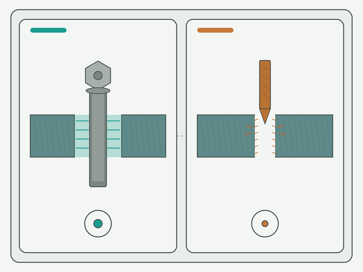
Schematic illustration: not a catalogue ranking or cutting-data table. Confirm clearance versus tap-drill intent on the drawing before picking a drill.
Nominal diameter and fit classes (close, normal, loose)
Clearance charts are keyed to nominal fastener diameter. Write the major size and the unit system before hunting a drill letter or millimetre stock.
- Inch family: #6, #8, #10, 1/4, 5/16, 3/8, 1/2, and similar majors. Thread naming is framed in the ASME B1.1 family; clearance recommendations for bolts, screws, and studs are framed in ASME B18.2.8. Use public standards literacy such as this codes and standards portal and this clearance holes for bolts screws and studs entry for naming only, not as a pasted standard substitute.
- Metric family: M3 through M12 and similar. Public metric tables often follow ISO 273-style fine / medium / coarse series, mapped in shop talk to close / normal / loose. National standards literacy such as this national standards overview supports naming ISO/DIN families only.
- Close fit: smallest practical clearance when the bolt helps locate parts or edge distance is limited. Demands better true position.
- Normal (standard) fit: default for most multi-fastener assemblies. If a print only says "clearance hole," many shops treat this as the working band until another class is named.
- Loose (free) fit: largest practical clearance for large patterns, weldments, thermal growth, or field assembly. Bearing area under the head shrinks; washers may be required by the print.
These fit labels are conditional practice, not an XRZ lab ranking that "normal always wins." The print, coating stack, and positional tolerance beat habit. Public screw tables such as this laboratory UNC/UNF screw table help teams name majors beside TPI when the traveler still carries a full callout like 1/4-20.
| Fit class (shop talk) | Typical intent | Tolerance budget tendency | Keep open when… |
|---|---|---|---|
| Close | Locate / tight alignment | Small positional error allowed | Pattern not matched or coating thick |
| Normal | General assembly default | Ordinary multi-hole drift | Print names another class |
| Loose | Maximum adjustment | Large stack-up / field fit | Bearing / washer note missing |
This compare table is conditional. It is not an unconditional ranking of close over normal or of any brand.
Inch clearance hole chart (selected common sizes)
The table below lists widely published inch clearance drills aimed at ASME B18.2.8-style close / normal / loose practice for common majors. Hole size depends on nominal diameter, not on TPI. Source boundary: public ASME B18.2.8-style clearance chart consensus as reflected in third-party engineering tables (cross-checked against this bolt clearance hole chart overview and this clearance hole chart for bolts and screws). Applicability: through-body clearance; commercial fit classes; coated fasteners may need a larger band. Verify against the drawing and drill inventory before production. Charts can disagree by one stock size; prefer the print over habit.
| Screw / bolt | Nominal Ø (in) | Close drill | Normal drill | Loose drill | Confirm when… |
|---|---|---|---|---|---|
| #6 | 0.1380 | #23 | #18 | #13 | Thin wall or coated screw |
| #8 | 0.1640 | #15 | #9 | #3 | Print names fit class |
| #10 | 0.1900 | #5 | #2 | B | Do not confuse with #10 tap drill |
| 1/4 | 0.2500 | 17/64 | 9/32 | 19/64 | 1/4-20 search intent; still keys on major |
| 5/16 | 0.3125 | 21/64 | 11/32 | 23/64 | Sister 5/16 tap-drill page is separate OWN |
| 3/8 | 0.3750 | 25/64 | 13/32 | 27/64 | Pattern true position tight |
| 1/2 | 0.5000 | 17/32 | 9/16 | 39/64 | Washer / bearing note on loose |
Source boundary: ASME B18.2.8-style inch clearance practice; public chart consensus; units inch letter/number/fractional. Decimal equivalents for the 1/4 row (teaching aid): close 17/64 ≈ 0.2656 in; normal 9/32 ≈ 0.2813 in; loose 19/64 ≈ 0.2969 in. Chart literacy, not XRZ measured results. Metrology literacy such as this public metrology laboratory entry and this weights and measures overview supports keeping inch decimals honest on the traveler.
1/4-20 clearance / thru hole worked note: searchers often ask for a "1/4-20 clearance hole" or "1/4-20 through hole size." Lock the 1/4-inch major first. Public charts commonly list 9/32 in (normal), 17/64 in (close), and 19/64 in (loose). The 20 TPI callout matters when the mating part is tapped (live 1/4-20 tap drill size for #7 cut-tap consensus); it does not replace the clearance row. Do not drill #7 (≈0.2010 in) and call it 1/4 clearance.
Metric clearance hole chart (selected common sizes)
Metric clearance holes are commonly listed as millimetre drill diameters in three series (fine / medium / coarse), which shops often map to close / normal / loose. Source boundary: public ISO 273-style metric clearance practice as reflected in the same third-party chart families cited above (standards naming via the DIN overview). Applicability: metric bolts/screws; verify drawing language before production.
| Bolt | Nominal Ø (mm) | Close / fine (mm) | Normal / medium (mm) | Loose / coarse (mm) | Confirm when… |
|---|---|---|---|---|---|
| M3 | 3.0 | 3.2 | 3.4 | 3.6 | Thin plate / coated screw |
| M4 | 4.0 | 4.3 | 4.5 | 4.8 | Print series unnamed |
| M5 | 5.0 | 5.3 | 5.5 | 5.8 | Do not swap to M5 tap drill |
| M6 | 6.0 | 6.4 | 6.6 | 7.0 | Common near-size to 1/4 inch stacks |
| M8 | 8.0 | 8.4 | 9.0 | 10.0 | Pattern stack-up large |
| M10 | 10.0 | 10.5 | 11.0 | 12.0 | Washer note on loose |
| M12 | 12.0 | 13.0 | 13.5 | 14.5 | Unit mix with inch prints |
Source boundary: ISO 273-style metric clearance series; public chart consensus; units millimetres. Unit conversion literacy such as this NIST SP 811 units guidance and this weights and measures program overview supports inch/mm discipline on mixed travelers. Do not eye-swap a 1/4 normal row (9/32 in) to "about 7 mm" without documenting the conversion and fit intent.
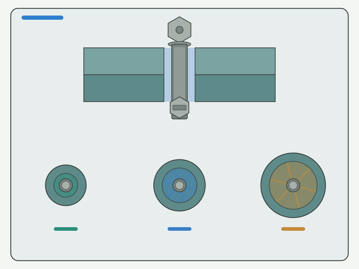
Schematic illustration: boundaries only, not a catalogue ranking. Confirm fit class, plate stack, and units on the drawing before picking a drill.
Plate thickness, coatings, and assembly conditions
A chart row is only the starting diameter. Stack and process conditions change whether close, normal, or loose is usable.
- Plate thickness and clamp length: thick stacks do not rewrite the clearance diameter by themselves, but they change how much angular misalignment a tight hole will fight. Prefer the fit the print names rather than shrinking the hole "for strength."
- Coatings and plating: zinc, paint, and powder builds reduce free clearance. Conditional practice often moves one band looser or calls a documented oversize. Write the coating system on the traveler; do not invent a coating % as an XRZ result.
- Multi-hole patterns: true position and center-distance error accumulate. Close fit on every hole in a large pattern often binds. Normal or loose may be honest when holes are drilled without matched tooling.
- Head bearing and washers: loose fit reduces bearing area under the head. Washer callouts and edge distance belong on the drawing beside the clearance drill.
- Drilling the clearance hole: browse carbide drill bits for a matched thru-hole drill. Process framing sits on the live precision holemaking selection guide.
| Condition | Tendency | Lock on the sheet | Do not invent |
|---|---|---|---|
| Coated fastener / painted stack | Often one band looser | Coating system + fit class | Fake coating % as XRZ data |
| Large bolt pattern | Normal or loose | True position / CD notes | "Close always stronger" |
| Single locating bolt | Close may be justified | Locate feature named | Life or ROI from fit class |
| Mixed inch/metric prints | Documented conversion | Unit system + major | Eye-swap 1/4 to M6 |
Toolholding literacy such as this tool holder technology overview and cutting-data literacy such as this cutting data notes portal support naming holder stiffness beside drill choice. Research society literacy such as this CIRP research portal frames process research boundaries only. CNC threading literacy such as this CNC threading and tapping overview helps keep tap-drill talk off the clearance traveler.
Common clearance-chart lookup mistakes
These mix-ups show up when "1/4-20" slang collides with thru-hole intent.
- Using a tap-drill row as clearance: #7 (≈0.2010 in) is a common 1/4-20 cut-tap starter, not a 1/4 clearance drill. Normal-fit 1/4 clearance is commonly 9/32 in on public clearance charts.
- Sizing from TPI instead of major diameter: 1/4-20 and 1/4-28 share the same 0.250 in major for clearance. TPI changes the tap drill, not the clearance key.
- Swapping #10 clearance with #10 tap drill: #10 clearance (for example #2 normal on many charts) is not the #25 / #21 tap-drill world. Soft-noted 10-32 deep dive (10-32 tap drill size) stays separate until live.
- Eye-swapping inch to metric: a 1/4 normal row is not automatically "M6 normal." Document units and convert with a named method.
- Assuming "clearance" always means close: many prints that omit the class expect a normal band. Close without true-position budget binds assemblies.
- Ignoring coatings: plated bolts in painted holes can seize a close band that looked fine on bare metal.
- Tapping a clearance hole: if the plate must hold a thread, leave this chart and open the live tap drill size chart path (and taps).
Public distributor help such as this tap drill sizes help page and this tap and drill size chart are literacy for the tap-drill side only (neutral anchors). Consolidated public tap charts such as this UNC UNF and metric tap drill chart show why those decimals must not be pasted into a clearance cell.
Worked examples (searchable intents)
These examples answer common queries at chart depth. Each still needs drawing fit class and process confirmation before production.
| Intent example | Lock first | Common chart starter | Page note |
|---|---|---|---|
| 1/4-20 clearance hole | 1/4 in major + fit class | Normal ≈ 9/32 in; close 17/64; loose 19/64 | TPI for naming only; not tap drill |
| 1/4-20 through hole size | Same 1/4 major | Same inch clearance row | Thru = clearance OWN |
| 1/4-20 thru hole size | Same 1/4 major | Same inch clearance row | Do not use #7 cut-tap |
| 1/4-20 through hole | Same 1/4 major | Same inch clearance row | Confirm coating / pattern |
| 5/16 clearance hole | 5/16 in major + fit | Normal ≈ 11/32 in | Tap-drill OWN on live 5/16 page |
| M6 clearance hole | M6 + series | Normal / medium ≈ 6.6 mm | Do not eye-swap to 1/4 |
| Need a tapped hole instead | Thread callout + method | Leave this chart | Use tap-drill siblings + taps |
Source boundary: same ASME B18.2.8-style / ISO 273-style public chart families as the tables above. Soft-note until live: 10-32 tap-drill deep dive (10-32 tap drill size).
| Boundary | Lock on the sheet | Fail signal | Do not invent |
|---|---|---|---|
| Intent | Clearance vs tap drill | Loose bolt or missing thread | Fake "universal 1/4 drill" |
| Fit class | Close / normal / loose (or print) | Bind or excess float | Best-fit ranking as XRZ data |
| Units | Inch or mm + conversion method | Wrong stock pulled | Eye-swap majors |
| Stack | Coating, pattern, washer notes | Seized head or pull-through | Life % from thickness |
| Drill SKU | Designation + decimal/mm | Out-of-tolerance hole | Price or ROI from drill letter |
Engineering calculator literacy such as this engineering calculators portal helps name unit math without inventing XRZ life data. Threading education such as this threading knowledge overview adds process naming only when the mating hole is threaded (neutral anchor).
Procurement checklist (RFQ inputs)
Send what you know. Leave life, price, and unverified cycle-time fields blank. Do not invent an unconditional best-clearance ranking.
- Drawing revision and hole intent (clearance / thru versus tap-drill versus counterbore stack).
- Fastener nominal major (inch or metric) and full callout if known (for example 1/4-20 for naming).
- Fit class: close, normal, or loose (or ISO fine / medium / coarse) and any print override.
- Proposed clearance drill size with units and chart family used.
- Unit note if the shop mixes inch and millimetre stock (documented conversion).
- Plate thickness, coatings/paint, washer notes.
- Hole pattern / true-position notes (usually through for clearance).
- Plate material and coolant intent for the drill.
- Acceptance method (pin gauge, functional bolt pass, CMM).
- Identifiers needed for repeat orders.
Browse live constructions here: carbide drill bits and taps (when the mating member is threaded). Open the request form when the package is ready: custom cutting tool RFQ.
Confirm the specification with engineering support
Before production ramp, confirm clearance versus tap-drill intent, nominal major with units, fit class, proposed drill, plate stack and coatings, pattern tolerance, and acceptance method. Hand the package to a product and RFQ path for a matched carbide drill recommendation. HENTRY / HC supports drawing-based drill proposals. No price, MOQ, or unverified lead time is stated on this page.
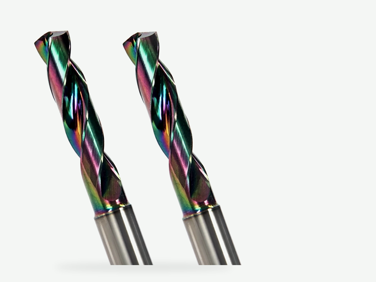
Specification fields to confirm
- Proposed clearance drill designation (fraction / letter / number / mm) and chart family.
- Fastener major: inch or metric; full callout if used for naming (for example 1/4-20).
- Fit class: close / normal / loose or ISO fine / medium / coarse.
- Plate material, thickness, coatings, washer notes.
- Pattern / true-position notes; through-hole confirmation.
- Unit system on the traveler (inch; documented mm if mixed).
- Inspection and sample acceptance expectations.
- Identifiers needed for repeat orders.
Trial plan (minimum)
- Same drawing revision and acceptance criteria as the checklist.
- First-off record of bolt pass/float, head seating, and measured hole size before compensation edits.
- Change one variable at a time when comparing close versus normal versus loose under the same coating and pattern intent.
- Stop when bolts bind, heads pull through, patterns will not assemble, or hole size drifts out of the print band.
- Do not claim a fit class "won" without those controls.
Review listed constructions here: explore carbide drill bits · explore taps. Research and practice portals such as this CIRP research portal (also cited above) and tooling resource literacy such as this tooling resources overview support industry literacy only.
Request a clearance-hole / drill recommendation
Suggested enquiry subject: Bolt clearance - [major] - [fit] - [material] - [coating] - [drill]
Bolt Clearance Hole Chart FAQ
What size clearance hole for a 1/4-20 bolt?
Clearance keys off the 1/4-inch major diameter, not the 20 TPI. Public ASME B18.2.8-style charts commonly list about 17/64 inch (close), 9/32 inch (normal), and 19/64 inch (loose). Many drawings that only say clearance imply a normal-fit band until the print names another class. Confirm coating and positional tolerance. Chart consensus, not an XRZ measured guarantee.
Is a 1/4-20 clearance hole the same as a 1/4-20 tap drill?
No. A tap drill leaves material so a tap can cut or form an internal thread (public cut-tap charts often list #7 at about 0.2010 inch for 1/4-20). A clearance hole is larger so the shank passes without thread engagement. Do not reuse the tap-drill row as clearance.
What does close, normal, and loose fit mean for clearance holes?
Close is the smallest practical clearance for locating or tight alignment. Normal is the common default for multi-fastener assemblies. Loose is the largest band for large patterns, field fit, or thermal growth. Conditional labels, not an unconditional ranking; follow the print.
What size clearance hole for an M6 bolt?
Public ISO 273-style metric charts commonly list about 6.4 mm (close/fine), 6.6 mm (normal/medium), and 7.0 mm (loose/coarse). Confirm drawing naming. Do not eye-swap an inch 1/4 row to M6 without a documented conversion.
Does thread pitch change the clearance hole for 1/4-20 versus 1/4-28?
For the same 1/4-inch major, clearance rows key to nominal diameter, not TPI. Pitch matters for tap-drill selection. Keep clearance and tap-drill on separate traveler lines.
How do coatings and paint affect clearance hole size?
Coatings and paint reduce free radial room. Conditional practice often moves one fit band looser or calls a documented oversize. Write the coating system beside the fit class; do not invent a coating % as an XRZ result.
Which inputs should I send in an RFQ for clearance-hole drill selection?
Send drawing revision, clearance versus tap-drill intent, nominal major with units, fit class, proposed drill with units, plate thickness and coatings, pattern notes, material and coolant intent, acceptance method, and trial notes. Leave unverified life and price blank.
When does this page not apply?
It does not apply when you need a tap-drill size instead of clearance; invented life percentages, prices, ROI, or case counts; an unconditional best-clearance ranking; a form-versus-cut encyclopedia; a soft-noted 10-32 tap-drill book; or when nominal size, fit class, units, and acceptance notes are missing. Fix the inputs first.
Sources and related guides
Outbound references support ASME B18.2.8-style and ISO 273-style clearance-hole naming, public inch/metric chart literacy, fastener mechanics, metrology and units portals, tap-drill contrast literacy, toolholding and cutting-data literacy, and manufacturing research portals cited in the body. The decision walkthrough is an HC editorial teaching aid, not a measured customer result. Sources checked 24 October 2026 (Asia/Shanghai).
- Codes and standards portal (public standards entry; linked in body)
- Clearance holes for bolts screws and studs entry (public standards entry; linked in body)
- Bolt clearance hole chart overview (third-party engineering reference; linked in body)
- Clearance hole chart for bolts and screws (third-party engineering reference; linked in body)
- Bolt science portal (third-party fastener mechanics literacy; linked in body)
- Laboratory UNC/UNF screw table (public lab table; linked in body)
- National standards overview (public standards entry; linked in body)
- Public metrology laboratory entry (public metrology entry; linked in body)
- Weights and measures overview (public metrology entry; linked in body)
- NIST SP 811 units guidance (public metrology entry; linked in body)
- Weights and measures program overview (public metrology entry; linked in body)
- CNC threading and tapping overview (third-party education; linked in body)
- Tap drill sizes help page (third-party distributor education; linked in body)
- Tap and drill size chart (third-party fastener education; linked in body)
- UNC UNF and metric tap drill chart (third-party reference; linked in body)
- Engineering calculators portal (third-party tooling education; linked in body)
- Threading knowledge overview (third-party education; linked in body)
- Tool holder technology overview (third-party education; linked in body)
- Cutting data notes portal (third-party tooling education; linked in body)
- CIRP research portal (third-party research society; linked in body)
- Tooling resources overview (third-party tooling literacy; linked in body)
Related live guides: tap drill size chart · 1/4-20 tap drill size · 5/16 tap drill size · form tap vs cut tap · precision holemaking selection guide · carbide drill bits · taps · Knowledge hub · custom cutting tool RFQ. A dedicated 10-32 tap-drill page will be linked after it publishes (soft-note until live: 10-32 tap drill size).