
This page helps CNC process engineers, programmers, and tooling buyers set face milling as a process: when to face mill, which cutter families fit (indexable face mills, monoblock PCD face mills, shell-style bodies), how to plan entry, exit, and radial engagement, how cutter diameter relates to face width, and how to keep parameter and surface talk qualitative before RFQ. Sister OWN stays on the live fly-cutter versus face-mill compare, milling tools hub, peripheral milling, and climb versus conventional guides. This page is face-milling process OWN; it is not a fly-cutter versus face-mill encyclopedia, face/shell/end taxonomy, slot-milling book, surface-marks encyclopedia, chatter overview, 2-versus-4 flute encyclopedia, coatings encyclopedia, size chart book, full SFM library, climb long guide, peripheral process book, or holemaking OWN, and it does not invent an unconditional ranking, price, or life claim.
Start from the live hub when you still need cutter-family framing: milling tools guide. When the open question is fly cutter versus multi-insert face mill, use the live fly cutter vs face mill guide. For side-edge context, use the live peripheral milling guide. For feed-sense gates on facing passes, use the live climb vs conventional milling guide. Live facing constructions stay on indexable face milling cutters and PCD monoblock face milling cutters; shell-style bodies sit on shell mills when arbor mounting is the path. When a small face or wall points to an end mill, browse carbide end mills. A face/shell/end taxonomy, slot-milling tools guide, milling surface-finish book, and machining-chatter diagnosis overview will be linked after they publish (soft-note until live). End-mill speeds and feeds stays a non-primary soft pointer here.
Quick answer
- Face mill when the job is a flat face (or a large land) and engagement can be planned: use a face mill, shell-style body, or monoblock facing cutter when the feature is facing, not a deep slot or a thin wall that only an end mill can enter. Lock material, face size, stock per pass, finish acceptance, and machine power before copying a neighbour's diameter.
- Set engagement from entry, exit, and radial width: name how the cutter enters and leaves the face, whether climb or conventional sense is intentional, and how much of the diameter is engaged (ae relative to Dc). Unplanned full-diameter plunge or harsh exit often marks the face and spikes load even when catalogue diameter looks right.
- Size diameter against face width, not habit: a cutter much smaller than the face needs more passes and overlapping cusp control; a cutter near or larger than the face can cover in fewer passes but raises power, fixturing, and entry/exit risk. Prefer a diameter that matches the face-width plan and the spindle/fixture budget rather than "bigger is always flatter."
- Next step: lock material, face width, stock, finish acceptance, engagement and diameter intent, then open RFQ with indexable, monoblock PCD, or shell-style intent open if needed. Speeds-and-feeds arithmetic is not this page's primary library.
Selection path (stop when a field is missing):
| Step | What you lock | If missing |
|---|---|---|
| 1 Material and face intent | Grade family, condition, face size / shoulders, finish acceptance (Ra band or visual policy) | Stop; recover the drawing and acceptance note |
| 2 Engagement plan | Entry path, exit path, climb/conventional sense, planned ae vs Dc | Do not pick diameter from habit alone |
| 3 Diameter vs face width | Workpiece face width, cutter Dc, number of passes / overlap policy | Keep diameter open; do not upsize blindly |
| 4 Machine and fixturing | Spindle power / torque band, table rigidity, clamp plan, arbor / holder, stick-out | Do not treat a large Dc as a free finish upgrade |
| 5 Cutter family intent | Indexable face mill, monoblock PCD face mill, shell-style body, or "open pending trial" | Flag if only a drawer SKU is known |
| 6 Trial and RFQ | Trial-cut record + matched RFQ package | Open RFQ with incomplete SKU if needed |
Jump: Purpose and cutters · Entry, exit and engagement · Diameter vs face width · Parameters and surface · Fault and selection · RFQ · Confirm · FAQ
Face milling purpose and cutter types
Face milling generates a flat by rotating cutting edges across a face so the primary engagement is on the face (and often a short peripheral land), not a deep side-wall slot. Name purpose and cutter family on the setup sheet before debating catalogue diameter slogans.
- Process purpose: clear stock from a face, establish flatness and height, and leave an accepted surface under a stated inspection method. Facing is not peripheral side-milling OWN (see live peripheral milling) or fly-cutter versus face-mill compare (see live fly cutter vs face mill).
- Indexable face mill: a multi-insert body carries replaceable inserts around the face and periphery. Shared edges support production stock removal when power and fixture allow. Live constructions sit on indexable face milling cutters.
- Shell-style / arbor-mounted body: many facing bodies mount as shell mills on an arbor. Arbor fit, face seating, and insert kit discipline matter as much as insert grade. Browse shell mills when mounting form is the open question; a full face-mill versus shell versus end-mill taxonomy remains soft-noted until live.
- Monoblock PCD face mill: a solid or monoblock PCD facing tool suits non-ferrous and other PCD-appropriate faces when edge quality and finish stability dominate and the shop can protect the diamond edge. Live constructions sit on PCD monoblock face milling cutters. Do not invent life percentages from substrate slogans alone.
- When an end mill owns the feature instead: small lands, pocket floors with walls, or features the face mill cannot enter belong to end-mill OWN. Use carbide end mills and leave flute-count encyclopedias on their own live pages. Do not force a large face mill into a feature it cannot enter.
Public milling literacy such as this milling knowledge overview and this machining formulas overview helps teams name face milling, insert engagement, and chip load without a universal catalogue ranking. Manufacturing society vocabulary such as this manufacturing society portal supports naming facing without inventing slang as a standard.
Entry, exit and engagement
How the cutter meets and leaves the face often decides marks and load more than a single diameter number. Lock entry, exit, and radial engagement before you treat a facing pass as "just plunge and feed."
- Entry path: roll-in, ramp, or programmed lead-in reduces shock compared with slamming a full-width face into the blank. Hard entry on a wide engagement can spike torque, mark the lead edge, and excite chatter on light fixtures.
- Exit path: a sudden exit at full engagement can leave a lip, pull a burr, or unload the spindle abruptly. Plan exit engagement so the last contact is intentional, not an afterthought.
- Radial engagement (ae vs Dc): name how much of the cutter diameter is cutting across the face. Near-full engagement raises continuous load; partial engagement changes chip thickness history and can favour climb or conventional sense depending on the machine and fixture. Sense gates stay on the live climb vs conventional milling guide; name sense when engagement and finish interact.
- Interrupted faces and shoulders: castings, bosses, and stepped faces change entry/exit every revolution. Record interruption notes; do not copy a continuous-plate recipe onto an interrupted face without a trial plan.
- Holder, arbor, and stick-out: engagement plans fail when the arbor is loose, the shell face does not seat, or stick-out rings. Toolholding literacy such as this toolholding overview and this tool holder technology overview belongs beside stick-out notes on stiff facing setups.
Practice portals such as this cutting tools practice overview and this CNC milling overview support reading chatter and load symptoms; they are not HC shop results. Standards literacy such as this codes and standards portal and this international standards overview frames industry naming only. National standards literacy such as this national standards overview adds naming context only.
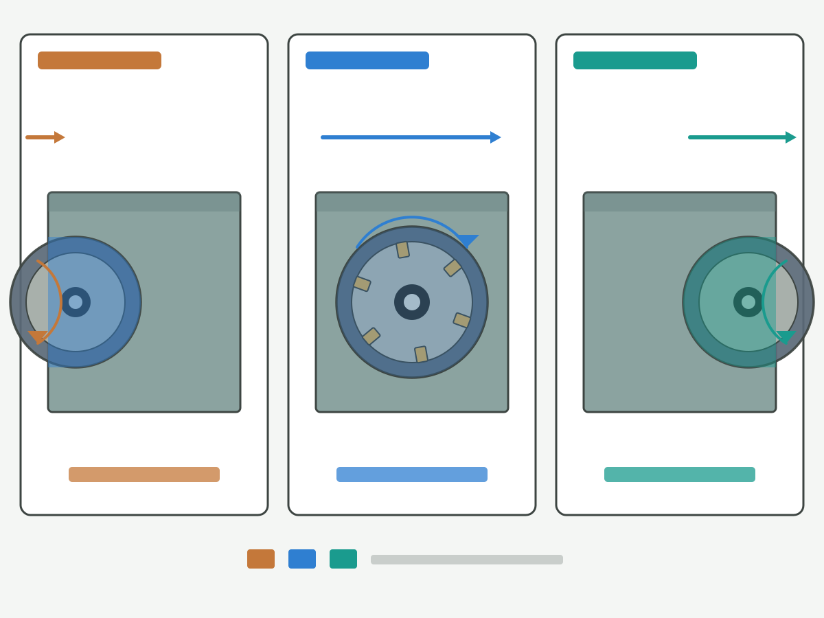
Schematic illustration: not a catalogue ranking or cutting-data table. Confirm entry path, exit path, ae versus Dc, and climb/conventional sense on your program and cutter data.
Cutter diameter versus face width
Cutter diameter (Dc) and workpiece face width set pass count, overlap, power demand, and entry/exit geometry. Treat diameter as a process variable tied to face width, not as a free cosmetic upgrade.
- Dc smaller than face width: multiple passes with controlled overlap are normal. Overlap must be named so cusp height and blend lines stay inside acceptance. More passes buy lower instantaneous engagement when power is limited, at the cost of cycle time and blend risk if overlap is sloppy.
- Dc near face width: one or few passes can cover the face when engagement is planned. Entry and exit become critical because a large fraction of the diameter may be cutting. Confirm fixture stiffness and usable power at the planned RPM.
- Dc larger than face width: the cutter can straddle a narrow face, which can help flatness when runout and insert height are controlled, but unused diameter still adds inertia, arbor demand, and collision risk at shoulders. Do not upsize "for finish" when the machine cannot sustain the engagement.
- Machine power and fixturing gate: diameter scales potential engagement area. An underpowered spindle or ringing fixture fails a large Dc even when the drawing face looks suitable. Keep diameter open on the RFQ when power or clamp notes are missing.
- Family still matters: indexable, shell-arbor, and monoblock PCD tools scale with Dc differently in spare policy and edge protection. Name family beside diameter.
Third-party tooling literacy such as this engineering calculators portal and this cutting data notes portal adds context for naming engagement and feed; neither is an HC trial result. Research society literacy such as this CIRP research portal frames process research boundaries only.
| Face-width vs Dc | Typical process note | Watch for | Escalate when… |
|---|---|---|---|
| Dc < face width | Multi-pass with named overlap | Blend lines, uneven cusp, wasted time if ae too timid | Overlap policy never written |
| Dc ≈ face width | Few passes; engagement fraction high | Harsh entry/exit, power spike, chatter | Power or clamp plan missing |
| Dc > face width | Straddle possible; fewer passes | Collision at shoulders, unused inertia, arbor demand | Diameter chosen only for a catalogue photo |
| Interrupted / stepped face | Engagement changes every rev | Marks at interruptions, tip/insert shock | Continuous-plate recipe copied blindly |
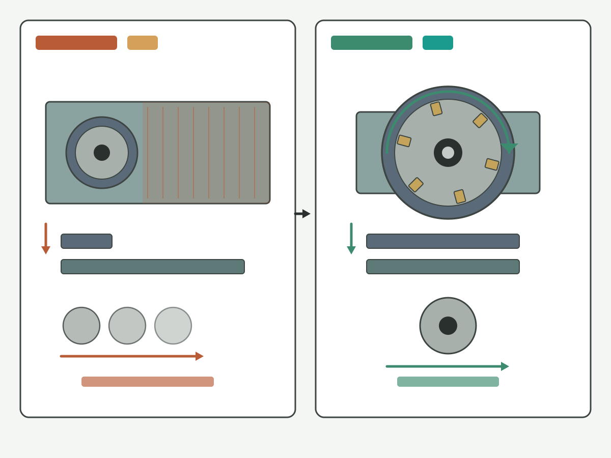
Schematic illustration: boundaries only, not a catalogue ranking. Confirm face width, Dc, pass count, and overlap on your drawing and cutter data.
Cutting parameters and surface boundaries (qualitative)
Parameters and surface quality belong together as boundaries, not as invented life curves. Keep numbers on the cutter data sheet and trial record; this page names what to lock.
- Depth of cut (ap) and radial engagement (ae): name stock per pass and how much of Dc is engaged. Heavy ap with near-full ae demands power and stiff fixturing; light finishing passes still need controlled entry/exit so marks do not replace the stock you just removed.
- Feed per tooth and table feed: multi-insert bodies share chip load across z edges when seating and runout are true. One high insert marks the face regardless of nominal fz. Record insert seating and runout checks beside feed intent.
- Surface character: insert layout, wiper use (when applicable), runout, and feed set visible cusp and swirl. Acceptance is Ra band, visual policy, or both. Do not invent an Ra promise from tool family alone. A dedicated milling surface-finish book remains soft-noted until live.
- Coolant / MQL / dry: name the mode beside material and edge type. Coolant literacy such as this coolant know-how overview supports naming flood, MQL, or dry without turning this page into a fluid encyclopedia.
- Metrology beside trial: metrology literacy such as this public metrology laboratory entry and this weights and measures overview supports naming Ra or visual acceptance beside trial numbers. Flatness and height still need the shop's own gauges and datums.
- Out of OWN here: full SFM libraries (end-mill speeds-and-feeds stays non-primary), coatings encyclopedias, size chart books, soft-noted chatter/surface-marks pages, and holemaking OWN.
| Boundary | Lock on the sheet | Fail signal | Do not invent |
|---|---|---|---|
| Stock / ap / ae | Stock per pass, ae vs Dc, pass count | Stall, chatter, uneven stock left | Life % from stock alone |
| Feed / z | fz intent, insert count, seating/runout check | Periodic face marks, one-insert lines | Price or ROI from feed slogans |
| Finish acceptance | Ra band and/or visual policy + method | Rejects without a named method | Ra promise from tool family alone |
| Coolant mode | Flood / MQL / dry named with material | Built-up edge or thermal marks unexplained | Unverified cycle-time claims |
Fault and selection boundaries (conditional)
Use this table as a conditional map, not an unconditional ranking. Prefer the column that matches the bottleneck you named. When both family and diameter remain open, keep them open on the RFQ and trial under the same acceptance method.
| Decision lens | Lean this way when… | Watch / alternate when… | Keep open / escalate when… |
|---|---|---|---|
| Feature is a face | Large flat / land; face mill or monoblock facing fits | Small land or wall points to an end mill | Feature type never named |
| Engagement plan | Entry, exit, ae vs Dc written | Harsh plunge or abrupt exit marks the face | Nobody will state sense or ae |
| Dc vs face width | Dc matches pass/overlap plan and power budget | Oversized Dc on light spindle or ringing fixture | Diameter chosen from habit only |
| Indexable multi-insert | Production facing; insert indexing routine; power available | Insert height / runout unchecked | Only a brand slogan is known |
| Monoblock PCD | PCD-appropriate material; finish stability prioritized; edge protected | Interrupted shock or ferrous misuse risk | Material suitability unconfirmed |
| Shell / arbor body | Correct arbor and face seating available | Improvised arbor fit | Mounting form unclear |
| Fault: chatter / marks | Reduce engagement, stiffen clamp, check seating, revisit entry/exit | Do not only upsize Dc for cosmetics | Chatter overview still soft-noted; escalate with trial data |
| RFQ posture | State family + Dc intent + engagement notes | Mark family/Dc open and attach trial plan | Inputs incomplete and nobody will stop |
A conditional table forces the bottleneck name onto the sheet. An unconditional "larger face mill is always better" slogan is not a process. Fly-cutter versus face-mill compare stays on its live guide when that is the open question.
Procurement checklist (RFQ inputs)
Send what you know. Leave life, price, and unverified cycle-time fields blank. Do not invent an unconditional facing-tool ranking.
- Drawing revision and face / land feature notes (size, shoulders, open face versus interrupted).
- Material grade, condition, and coolant / MQL / dry intent.
- Face width, stock per pass, number of passes, and planned ae versus Dc.
- Entry / exit plan and climb versus conventional sense if known.
- Finish acceptance (Ra band, visual policy, or both) and inspection method.
- Machine class, usable spindle power / torque band at planned RPM, table rigidity notes.
- Fixture clamp plan, support under the cut, arbor / holder type, and stick-out method.
- Cutter-family intent: indexable face mill, monoblock PCD face mill, shell-style body, or open; insert or edge notes if known.
- Trial-cut notes and acceptance method; identifiers for repeat orders.
Browse live constructions here: indexable face milling cutters and PCD monoblock face milling cutters. When arbor mounting is open, browse shell mills. When a small face or wall points to an end mill instead, browse carbide end mills. Open the request form when the package is ready: custom cutting tool RFQ.
Confirm the specification with engineering support
Before production ramp, confirm material condition, face width, stock per pass, engagement and diameter intent, finish acceptance, machine power band, and fixture plan with engineering. Hand the package to a product and RFQ path for a matched face-milling recommendation, not a catalogue guess. HENTRY / HC supports drawing-based indexable face-milling, monoblock PCD face-milling, and shell-mill proposals. No price, MOQ, or unverified lead time is stated on this page.
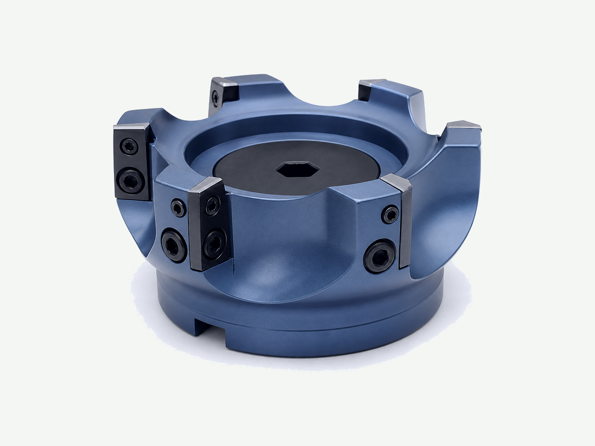
Specification fields to confirm
- Proposed tool model or drawing (indexable face mill / inserts, monoblock PCD face mill, or shell body + arbor).
- Material grade / condition and coolant mode.
- Face width, stock per pass, ae / ap bands, and Dc intent.
- Entry / exit plan and sense if known.
- Finish acceptance method (Ra and/or visual).
- Machine power / torque band, fixture clamp plan, arbor / holder, stick-out.
- Cutter-family intent (indexable, monoblock PCD, shell-style, or open).
- Inspection and sample acceptance expectations.
- Identifiers needed for repeat orders.
Trial plan (minimum)
- Same drawing revision and acceptance criteria as the checklist.
- First-off record of load, chatter, face marks, size, and flatness before compensation edits.
- Change one variable at a time when comparing diameter, engagement, or cutter family under the same stock and acceptance intent.
- Stop when chatter grows, marks look abnormal, size drifts, or the tool collides with the envelope.
- Do not claim a diameter or family "won" without those controls.
Review listed constructions here: explore indexable face milling cutters · explore PCD monoblock face milling cutters · explore shell mills · explore carbide end mills. Research and practice portals such as this CIRP research portal (also cited above for process research framing) and ISO public information such as this international standards overview support industry literacy only.
Request a face-milling recommendation
Suggested enquiry subject: face milling - [material] - [face width] - [stock / finish] - [Dc / engagement] - [family]
Face Milling FAQ
When should I use face milling?
Use face milling when the feature is a flat face or large land and a facing cutter can engage it with a planned entry, exit, and radial width. Prefer an end mill when the feature is a small land, pocket floor with walls, or envelope the face mill cannot enter. Lock material, face size, stock, and finish acceptance before copying a neighbour's diameter.
How do I set entry, exit, and engagement?
Name the entry path (roll-in, ramp, or controlled lead-in), the exit path, climb versus conventional sense, and ae relative to cutter diameter. Avoid slamming full-width engagement or exiting abruptly when marks and load matter. Record interruption notes on castings and stepped faces. Sense detail stays on the live climb versus conventional guide.
How should cutter diameter relate to face width?
Match diameter to the pass and overlap plan and to the spindle and fixture budget. A smaller diameter needs more passes with named overlap; a diameter near or larger than the face can cover in fewer passes but raises power, entry/exit, and collision risk. Do not upsize diameter for cosmetics alone on an underpowered or loosely clamped machine.
Indexable face mill, shell mill, or monoblock PCD: which family?
Lean indexable multi-insert when production facing and insert indexing fit the cell and power is available. Lean shell-style when arbor mounting and face seating are the path. Lean monoblock PCD when the material is PCD-appropriate and finish stability with edge protection dominates. Keep family open on the RFQ when suitability is unconfirmed. Do not invent life percentages from substrate slogans.
What surface and parameter boundaries should I lock?
Lock stock per pass, ae versus diameter, feed and insert-count intent with seating and runout checks, finish acceptance method, and coolant mode. Fail signals include stall, chatter, one-insert face lines, and rejects without a named inspection method. Do not invent Ra promises, life percentages, prices, or ROI on this page. Full SFM libraries and surface-marks encyclopedias sit outside this OWN.
Which inputs should I send in an RFQ for face milling?
Send drawing revision, material and coolant intent, face width, stock per pass, planned ae versus diameter, entry and exit notes, finish acceptance, machine power band, fixture and arbor or holder notes, cutter-family intent or open, trial notes, and acceptance method. Leave unverified life and price fields blank.
Does this page replace the fly-cutter vs face mill, milling tools, or peripheral milling pages?
No. Fly-cutter versus face-mill compare, milling-tools navigation, peripheral milling, and climb versus conventional each keep their live OWN. A face/shell/end taxonomy, slot-milling guide, surface-finish book, and chatter overview remain soft-noted until live. This page owns face-milling purpose and cutter types, entry/exit and engagement, diameter versus face width, qualitative parameter and surface boundaries, the conditional fault and selection table, and the RFQ checklist only.
When does this page not apply?
It does not apply when you need invented life percentages, prices, ROI, or unverified case counts; when you need an unconditional best-face-mill ranking; when you need a fly-cutter versus face-mill encyclopedia, face/shell/end taxonomy, slot-milling book, surface-marks encyclopedia, chatter overview, 2-versus-4 flute encyclopedia, coatings or size-chart books, full SFM library, climb long guide, peripheral process book, or holemaking OWN; or when material, face width, stock, finish acceptance, and engagement or power notes are missing. Fix the inputs first.
Sources and related guides
Outbound references support milling and formula literacy, toolholding and coolant boundaries, standards and metrology portals, cutting-data literacy, CNC milling practice, and manufacturing research portals cited in the body. Manufacturer-specific cutting data remain tied to their own products. The decision walkthrough is an HC editorial teaching aid, not a measured customer result. Sources checked 22 October 2026 (Asia/Shanghai).
- Milling knowledge overview (third-party education page; linked in body)
- Machining formulas overview (third-party education page; linked in body)
- Toolholding overview (third-party education page; linked in body)
- Tool holder technology overview (third-party education page; linked in body)
- Coolant know-how overview (third-party education page; linked in body)
- Engineering calculators portal (third-party tooling education; linked in body)
- Cutting data notes portal (third-party tooling education; linked in body)
- Codes and standards portal (public standards entry; linked in body)
- Public metrology laboratory entry (public metrology entry; linked in body)
- Weights and measures overview (public metrology entry; linked in body)
- National standards overview (public standards entry; linked in body)
- International standards overview (public standards entry; linked in body)
- Manufacturing society portal (public manufacturing literacy; linked in body)
- CIRP research portal (third-party research society; linked in body)
- Cutting tools practice overview (third-party education page; linked in body)
- CNC milling overview (third-party education page; linked in body)
Related live guides: milling tools guide · fly cutter vs face mill · peripheral milling · climb vs conventional milling · indexable face milling cutters · PCD monoblock face milling cutters · shell mills · carbide end mills · custom cutting tool RFQ. A face/shell/end taxonomy, slot-milling tools guide, milling surface-finish book, and machining-chatter diagnosis overview will be linked after they publish (soft-note until live). End-mill speeds and feeds stays a non-primary soft pointer here.