

CREATE THE HOLE
Solid carbide drill
First choice for through and blind holes from about 1 to 20 mm. Point geometry, flute count and coolant route are matched to material and depth ratio.
Drill rangeMost tooling mistakes are not made at the tool catalogue. They are made at the drawing, where a tolerance, a batch size and a machine capability are read in the wrong order, and a tool is chosen that cannot deliver the number.
This page is the order we use when quoting: feature first, material second, tolerance third, batch fourth, and only then the tool body, the holder and the coolant.
What this is: a selection sequence for CNC cutting tools, from the feature on the part to the tool family, the substrate and the number of stations, with the decision points that change the price.
Which process and material: solid carbide drilling, reaming, milling and tapping for steel, stainless, cast iron and aluminum; PCD tooling for aluminum, high-silicon aluminum and other abrasive non-ferrous work; CBN for hardened steel above the carbide range.
Why us: the same supplier makes the drill, the reamer and the step tool, so a feature that fails is diagnosed against one sample report instead of being passed between three catalogues.
A tool is only as good as the constraint it was chosen against. Reading the drawing in the wrong order produces a technically correct tool that cannot hold the callout, or a tool that holds it at twice the cycle time.
The sequence below is deliberate: each step removes options before the next step is considered, so the last decision (which catalogue item) is almost automatic.
| Order | Decision | What it rules out | What it does not decide |
|---|---|---|---|
| 1 | Feature type: hole, bore, thread, slot, face, profile | Whole tool families that cannot make the shape | Size, tolerance, coating |
| 2 | Material and condition | Substrates and coatings that fail by wear or adhesion | Number of flutes, tool length |
| 3 | Tolerance and surface callout | Single-pass processes that cannot reach the band | Whether a second station is economic |
| 4 | Batch size and expected life | Solid versus indexable versus custom form | Holder and coolant route |
| 5 | Machine, holder and coolant | Tools that need runout or pressure the shop does not have | Supplier and lead time |
| 6 | Cost per part | Options that pass every technical test but lose money | Nothing; this is the closing test |
Tolerance bands and process statements here are industry starting points for choosing a path, not an HENTRY specification. The number we stand behind is the one measured on your first article, with material, holder and coolant recorded next to it.
The feature decides the family before any dimension is read. A through hole in a plate and a bearing bore in a housing can share a diameter and share nothing else: one needs position, the other needs roundness and finish.
| Feature | Tool family | Typical path | Where it goes wrong |
|---|---|---|---|
| Through or blind hole, general tolerance | Solid carbide drill | Spot if needed, drill to size | Walk on thin plate, exit burr |
| Precision bore or locating hole | Reamer, or boring bar above roughly 20 mm | Drill undersize, ream or bore | Expecting the reamer to correct position |
| Thread | Tap, thread mill, or forming tap | Drill tapping size, then tap or mill | Tapping drill too small in gummy material |
| Slot, pocket, square shoulder | Square or corner radius end mill | Rough, then finish with a separate pass | Using one tool for both roughing and finish |
| Face or large flat | Indexable face mill, shell mill | Rough, then finish | Insufficient rigidity for the insert count |
| Freeform or thin wall profile | Ball nose, tapered, or lollipop mill | Constant stepover, light radial load | Tool deflection on long reach |
| Counterbore or spotface | Step drill or coredrill | One pass instead of two stations | Seat not square to the through hole |
Two families are frequently confused. A combination drill and reamer removes a station, but it cannot fix a position error, because the reaming section still follows the drilled hole.
A step tool removes a station and holds a shoulder, but only if the shoulder and the bore are called out on one axis.
Aluminum fails tools by built-up edge and adhesion. Stainless fails them by work hardening and heat at the edge. Cast iron fails them by abrasion. Hardened steel fails them by heat and notch wear. Four mechanisms, four different answers.
| Work material | Substrate | Coating or finish | Failure to expect |
|---|---|---|---|
| Aluminum, low silicon | Fine grain carbide, polished flutes | Uncoated or DLC-type low friction | Built-up edge, torn finish |
| High-silicon aluminum, cast | PCD or diamond-coated carbide | PCD edge | Abrasive flank wear, size drift |
| Carbon and alloy steel | Carbide, toughness grade | AlTiN or TiAlN | Crater and flank wear at speed |
| Stainless, austenitic | Carbide, sharp edge, high toughness | AlTiN, thin and smooth | Work hardening, chipping on entry |
| Cast iron, grey or ductile | Carbide, wear resistant | AlTiN or TiCN | Abrasion, edge rounding |
| Hardened steel above 45 HRC | Carbide micrograin or CBN | AlTiN or none for CBN | Notch wear, edge break down |
| Graphite, CFRP, composites | Diamond-coated carbide or PCD | Diamond | Delamination and fraying at exit |
Coating is not a ranking. A hard coating on a gummy aluminum alloy increases edge friction and makes the built-up edge worse, which is why uncoated polished tools still win there.
Material condition matters as much as the alloy name. The same 6061 in T6 and in an annealed state behaves differently, and a cast surface with sand inclusion wears an edge faster than the drawing suggests.
If the callout is IT8 or tighter, a drill alone is not a plan. The ladder below is the general capability order, and the step from one rung to the next is what adds a station, a tool and a cost line.
| Process | Typical band | What it fixes | What it cannot fix |
|---|---|---|---|
| Drilling | About IT11 to IT13 | Creates the hole at low cost | Roundness, finish, position beyond the drill |
| Drill and ream | About IT7 to IT9 | Diameter, roundness, finish | Position, taper from an offset pre-hole |
| Drill and fine bore | About IT6 to IT7 | Size, straightness, position correction within cut | Very small diameters, deep holes |
| Grinding or honing | IT5 and tighter | Roundness, finish, size after heat treatment | Position, unless the setup controls it |
Surface callouts move the same way. A reamed bore in steel typically lands around Ra 0.8 to 1.6 micrometres as a starting expectation, while a drilled hole sits several times rougher.
If the print asks for a mirror finish in aluminum, the answer is usually a PCD reamer or a burnishing pass, not a sharper drill.
Position is the callout most often misassigned. It is set by the drill, the spot and the fixture, and no downstream sizing tool recovers it. The arithmetic for a hole pattern is worked through in box and bracket hole patterns.
Three tool forms cover most production. Solid carbide gives the best accuracy per euro at small diameter. Indexable gives a fresh edge in seconds at large diameter. A custom form tool collapses several stations into one but only pays back over a batch.
The comparison is not tool price. It is cost per good part: tool cost divided by parts per tool life, plus cycle time multiplied by machine rate, plus scrap rate multiplied by part cost.
| Tool form | Best when | Cost driver | Risk |
|---|---|---|---|
| Solid carbide, standard | Small diameter, high accuracy, short lead time | Parts per regrind | Breakage on interrupted cuts |
| Solid carbide, custom step or form | Two or three features on one axis, medium to high volume | Tooling lead time and first-article cost | Design freeze; a print change scraps the tool |
| Indexable | Large diameter, mixed batch, unattended running | Insert cost per edge | Runout and pocket repeatability |
| Brazed or PCD-tipped | Abrasive non-ferrous, long runs | Initial price, regrind count | Impact damage on interrupted cuts |
We do not publish price lists, because the same tool costs different amounts at different diameters and coating combinations.
What we do publish is the break-even logic: if a custom tool removes one station and one handling step, it usually pays back inside a few thousand parts. Below that volume the standard tool is the honest recommendation.
The station count is also a quality decision. Every extra station is another clamping, another datum repeat and another chance to lose position, which is why a combination tool is often chosen for consistency rather than for cycle time.
A drill selected for a 0.02 mm runout holder will not deliver its position on a collet chuck with 0.05 mm runout and a worn taper. The tool is not wrong; the interface was never part of the selection.
Runout loads one flute harder, which shows up as size drift, a tapered hole and a shorter life, and it shifts the hole slightly on entry. On a reamer it produces an oversize, lobed bore that no allowance change will fix.
| Interface | Strength | Watch out for |
|---|---|---|
| Hydraulic chuck | Low runout, good damping, fast change | Clamping range and cleanliness of the bore |
| Shrink fit | Very low runout, high torque at small diameter | Thermal cycle time, limited tool changes |
| Collet chuck | Flexible range, low cost | Runout grows with wear and with chip in the collet |
| Side-lock or whistle notch | High torque for roughing | Induced eccentricity on precision work |
Coolant is the other half. Through-tool coolant is what makes a deep hole predictable, and its absence is a common reason a tool that worked in one shop fails in another. Where through coolant is not available, pecking and external flush change the depth limit, not the tool geometry.
These are the tools that appear in most quotes we write. The full range is on the product pages; the point here is which one a given feature pulls in.
First choice for through and blind holes from about 1 to 20 mm. Point geometry, flute count and coolant route are matched to material and depth ratio.
Drill range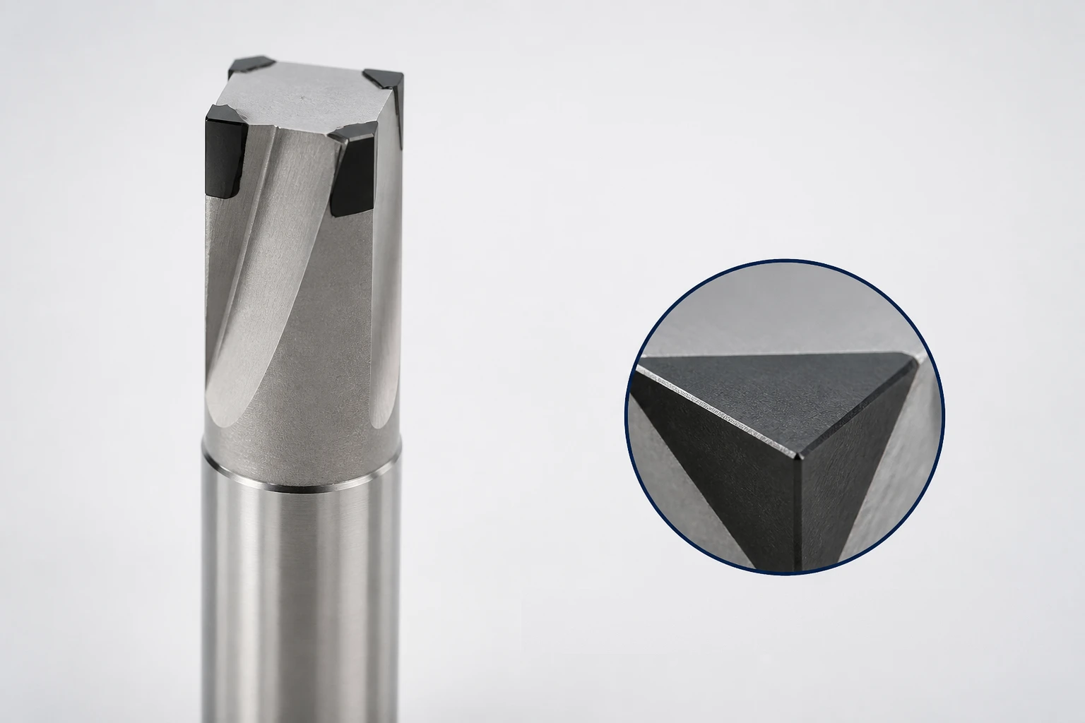
For aluminum, high-silicon aluminum and abrasive non-ferrous pockets and shoulders, where a carbide edge wears by abrasion within one batch.
PCD end mill range
Sizes a bore that is already in position. Holds diameter and finish in abrasive aluminum, but never corrects the position the drill delivered.
PCD reamer rangeThese are general technical references on tool selection by feature and material. They are not supplier recommendations, and we have no affiliation with the publishers.
The process. Feature, material, tolerance and batch decide whether the part needs one station or three. The tool is then whichever body delivers that process on your machine.
No. For short runs and simple shapes, polished carbide is cheaper and adequate. PCD earns its price in high-silicon castings, long runs and abrasive alloys where carbide edges wear within a batch.
When the two features share an axis, the batch is repeatable, and the print is stable. It removes a station and a datum repeat. If the print is still moving, a custom tool is money at risk.
No. It follows the pre-hole. Position comes from the drill, the spot and the fixture; a reamer only changes diameter, roundness and finish.
It changes runout, and runout changes size, finish and life. On a hole with a 0.05 mm position callout it usually matters more than the difference between two drill brands.
Send the drawing or the feature list with material, tolerance, batch size, machine and holder. We reply with the process path, the tool recommendation per feature and the sample plan.