
The RFQ says “PCD reamer, aluminum housing,” and the sketch shows three different bores on one casting: a deep blind oil gallery, a through bearing seat, and a cross hole that opens into a window. One catalog body will not serve all three. Chip packing kills the blind; exit breakout kills the through; every window edge hammers the land on the interrupted cut. Scrap starts as the wrong guidance, lead, flute volume, or coolant path—not as “PCD failed.”
This page owns the hole-type decision for a PCD reamer: how guidance (pads/pilot), lead geometry, flute space, and coolant change across blind, through, cross, and interrupted bores. It does not rewrite drill interrupted / cross-hole create. It does not rewrite deep-blind combination risks. Allowance and pre-hole quality stay on their own pages; send those fields with the sketch when you RFQ.
Blind holes punish chip packing and weak coolant; through holes shift risk to exit edge and breakout; cross and interrupted cuts hit the PCD land hard at each window. Guidance (pads/pilot), lead geometry, flute volume, and coolant path must follow the hole type—not a generic “PCD reamer” catalog pick. Send a sketch of hole type, depth, intersections, and scrap mode. XRZ reads the drawing with you, writes first-article accept before metal, and stays on first-off (sample validation · how PCD reamers are made · RFQ checklist).
1. Decision table: hole type → risk, structure, data, validation
Tuesday’s RFQ often asks for “one PCD reamer” and a flute-count slogan. Use this as an engineering heuristic map (inference), not a universal flute-count or coolant-bar table. Plant diameter, L/D, machine rigidity, and scrap mode still win.
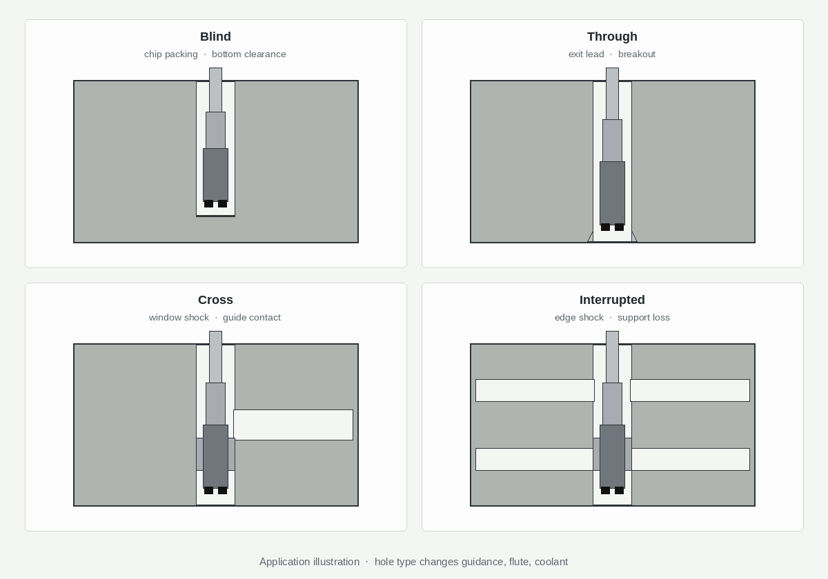
| Hole type | Main risk | Structure tendency | Must-confirm data | Validation |
|---|---|---|---|---|
| Blind | Chip packing; starved coolant at bottom; land rub when chips wedge | More flute volume / evacuation path; through-coolant or directed flow when depth packs; bottom clearance; do not force an over-long cutting length “just in case” | Depth, bottom geometry, coolant ports/pressure, chip photo, L/D | First-article: bottom finish, chip form, no burn/rub marks; written accept on packing scrap mode |
| Through | Exit breakout / burr; exit land overload; sudden unload | Lead / exit chamfer strategy; exit feed or dwell plan; flute enough for continuous chip; guidance that does not over-constrain exit | Exit condition (free / into pocket), burr spec, lead angle on drawing, feed-out method | First-article: exit burr/breakout, IT/Ra at exit vs mid-bore (accuracy / finish) |
| Cross | Impact at each window; guide loss across opening; chip catch at intersection | Lead and land that survive intermittent load; guide pads/pilot only if they still contact solid wall; flute that clears chips at junctions | Intersection sketch, window size/clock, entry vs exit side, scrap photos | First-article across the intersection zone; check lobing after windows—not only at solid entry |
| Interrupted | Repeated edge shock; micro-chipping; guide chatter when support drops | Stronger edge prep / lead for shock; reconsider pad count/placement; do not copy a continuous-bore reamer | Interrupt pattern, RPM/feed at interrupt, prior tool failure mode | First-article after the agreed window count, edge photo, bore after last window |
Dedupe sentences (keep): Cross and interrupted create belongs on the carbide drill interrupted-cut / cross-hole page. Deep-blind combination tooling risks stay on deep-blind PCD combination risks. This page decides reamer guidance, lead, flute, and coolant for the finish bore.
Pre-hole size and quality still gate every row: reaming allowance / pre-hole size · pre-hole quality.
2. Blind bores: flute space, coolant, bottom clearance
A blind PCD ream fails quietly: chips stop moving, the land rubs, Ra climbs, and someone blames “dull diamond.” The mechanism is packing and heat at the closed end.
What to change on the reamer (tendency, not a bar chart):
- Flute volume and evacuation path matter more than catalog flute count slogans. Deep blind with sticky aluminum chips needs space and a path out—not a long land that traps swarf.
- Coolant: through-coolant or a directed port aimed at the cutting zone when L/D and packing history say flood never reaches the bottom. Blind does not always equal “must be through-coolant”—see FAQ—but if chips burn or wedge at depth, coolant path is a first lever.
- Bottom clearance: leave geometry that does not rub the floor or leave a chip pocket against a flat land.
- Cutting length: do not specify an over-long PCD section “for future depths.” Extra length in a blind bore is extra rub surface when chips stall.
When the print is a deep blind combo (drill + ream or multi-feature in one body), stop and open deep-blind combination risks before you force a single long reamer. Combination risk is not the same as “pick a longer flute.”
Scrap modes that point to blind structure: packed flutes on pull-out, burnished bottom, sudden oversize after a few holes, blue/heat tint on chips only at depth.
3. Through bores: exit lead, breakout, exit strategy
Through holes move the failure to the exit. The land leaves support, the chip thins or breaks, and exit burr or breakout scrap the part even when mid-bore IT looks fine.
Structure tendencies:
- Lead and/or exit chamfer on the tool (or a controlled exit plan) so the edge does not unload into a sharp wall.
- Exit feed, dwell, or approach from the opposite side when the process allows—write the method; do not leave it to “operator feel.”
- Guidance that still helps mid-bore without forcing a pad across an exit into free air in a way that chatters.
Link accuracy and burr diagnosis when the scrap photo is exit-side: hole accuracy and surface finish. Multi-diameter through seats may need step-form / when to RFQ a step reamer—that page owns contour steps; this page owns hole-type exit behavior.
Must-confirm: Is the exit free, into a pocket, or into a machined face with a burr callout? That single sketch note changes lead and feed-out more than a generic “through reamer” label.
4. Cross and interrupted: edge shock, guide stability—ream side only
At each window the PCD edge enters and leaves metal. That is intermittent cutting on the finish reamer, not the create drill story.
What changes:
- Edge / lead: tend toward a lead and edge preparation that absorbs shock better than a razor continuous-bore grind—still validate on your alloy and Ø; no universal hone table here.
- Guide pads / pilot: only keep pads that still find solid wall. A pad that “flies” across a large window can chatter or mark. Pad clock vs window clock belongs on the sketch.
- Flute: clear chips at the intersection so a slug does not reload into the next land.
Explicit non-rewrite: Drill point geometry, peck, and create-side cross-hole tactics stay on carbide drill interrupted cut / cross hole. Soft-link that page; do not paste its drill checklist into a reamer RFQ and call it done.
If the same casting needs create + finish, send both scrap modes: drill break at the window vs reamer land chipping after the window. They are different tools and different levers.
5. RFQ pack + service loop (hole-type sketch → written accept → first-off)
The catalog pick is the wrong ending. The useful path is a process loop:
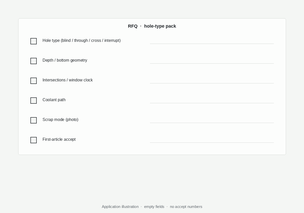
- Receive the hole-type sketch (blind / through / cross / interrupt pattern), depth, intersections, coolant ports, scrap photos, plus allowance and pre-hole notes from the linked pages.
- Write acceptance: what first-article must pass (IT/Ra zones, exit burr, packing, edge photo after interrupts).
- Sample / first-off stay: run the agreed checks; freeze offsets and tool revision before volume (sample validation).
Hole-type fields for the RFQ
- Hole type per bore (blind / through / cross / interrupted) and a dimensioned sketch
- Depth, L/D, bottom and exit conditions
- Intersection / window size and clock
- Coolant: flood / through / pressure-flow if known
- Scrap mode and where it appears (entry / mid / exit / after window)
- Pre-hole process and allowance reference (allowance · pre-hole quality)
- Material, IT/Ra, machine / holder interface
Checklist → PCD Reamer RFQ Checklist → Custom Cutting Tool RFQ. Product: Custom PCD Reamer. Grind and inspect context: how PCD reamers are made.
Frequently Asked Questions
Do blind holes always need through-coolant on a PCD reamer?
No. Blind geometry raises the risk of packing and starved cooling, so through-coolant or directed flow is a strong lever when depth, sticky chips, or burn marks already show up. Shallow blinds with reliable flood and short chips may run without through ports. Decide from L/D, chip photos, and scrap mode—not from a slogan. Put coolant ports and pressure in the RFQ sketch.
Can the same reamer run through and cross holes?
Sometimes on similar Ø and continuous wall sections, but a large cross window changes guide contact and edge shock. If pads lose wall or the scrap mode flips from exit burr to land chipping, treat them as different structure decisions. Send both hole types on one sketch rather than assuming one body covers the casting.
How does interrupted cut change guide-pad / lead choices?
Interrupts favor a lead and edge that tolerate shock, and pads only where solid contact remains across the pattern. A continuous-bore pad layout can chatter or mark when it flies a window. Clock pads vs windows on the drawing. Create-side interrupt tactics stay on the drill interrupted / cross-hole page.
What hole-type data belongs in an XRZ RFQ?
Per bore: type (blind/through/cross/interrupted), depth, exit/bottom, intersection sketch, coolant path, scrap mode and location, pre-hole/allowance notes, material, IT/Ra, machine/holder → RFQ checklist → sample validation → Custom Cutting Tool RFQ.
Next step
The best ending is not one “aluminum PCD reamer” for every bore on the casting. It is a hole-type sketch we both read the same way, written first-article accept, and someone still answering when the blind packs or the exit breaks out.
Related: PCD grain size & edge prep.