
A PCD reamer can be ground to a 21 um band and still miss H7 in a machine that cannot hold its own position.
Before anyone changes the tool, we measure five machine-side variables: radial runout at the cutting edge, thermal growth, the toolholder interface, coolant pressure and axis resolution.
Each one has a field check that fits inside an hour, and a failure signature you can see on the parts.
Machine-side problems usually look like a bore that is correct when the spindle is cold and wrong two hours later, or correct in one setup and wrong after a tool change.
Check runout at the cutting edges first, thermal drift across a shift second, holder and stickout third, coolant delivery fourth, and feed axis resolution last. If all five pass and the bore is still out, the pre-hole is the next suspect, not the machine.
This page sits under the wider PCD reamer technical centre, where the tool side of the same decision is covered. Here we stay on the machine.
Radial runout at the cutting edge: the reading that decides the cut
A finishing reamer removes a small allowance with several edges at once, so each edge takes a thin chip. If the assembly runs out, one edge cuts more than the others and the rest rub.
The bore then comes out oversize and out of round at the same time, and the operator changes the tool, which was never the problem.
We ask for runout measured on the cutting edges, with the reamer clamped as it will run, not on the shank and not on a bare spindle taper.
The check: a dial indicator on the flutes or on a ground test bar, rotate the spindle by hand through one turn, read total indicator movement. A working starting point for finishing work is around 5 um TIR at the edge, and it is a starting point, not a HENTRY acceptance limit.
How the assembly is set and re-checked off the machine is in presetting and runout checks for PCD reamers.
The signature is easy to recognise once you know it: size spread roughly twice the runout, and a two-lobe roundness trace on a bore that a two-point micrometer called good.
Where we can be wrong: a low reading on a test bar does not prove the reamer seats the same way, because the clamp, the shank tolerance and the taper contact all change with the tool in place. Ask for the reading with the reamer mounted.
Runout is judged with the reamer clamped, on the spindle and holder it will actually run on. The reference readings used on this page are shop starting points, not HENTRY specifications, and each plant should tighten them to its own tolerance band.
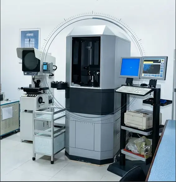
Thermal growth: why the morning parts and the afternoon parts differ
The second shift runs the same program, the same tool and the same coolant, and the bore moves 4 or 5 um. Nobody changed a parameter. What changed is temperature: the spindle, the ballscrew, the fixture and the part all grew since the first part of the morning.
For orientation, aluminium expands about 23 um per metre per K. At a 20 mm bore that is roughly 0.5 um per K, so a 10 K swing between a cold morning and a warm afternoon is worth about 5 um on the part alone, before spindle growth is counted.
We treat 0.5 um per K at 20 mm as a working figure for aluminium and check it against the alloy rather than assuming it.
The field check is a master ring or a first-off part measured at the start of the shift, again after two hours and again at the end, with spindle temperature written next to each reading. A stable machine drifts by less than a third of the tolerance band across a shift.
The signature is the split you can see on a control chart: the morning parts sit at one end of the band and the afternoon parts at the other, with no change in spread.
More on reading that pattern is in chatter and vibration diagnosis, which starts from the same measurement discipline.
What we cannot tell from a single reading: whether the drift came from the spindle, the coolant, the fixture or the part. Separating them needs the temperature log, not one number.
Toolholder interface: stickout, clamping and the exit cone
A hydraulic chuck and a shrink-fit holder both hold a finishing reamer well, and both are a different proposition from an ER collet that has been in the cell for three years.
The variable that decides the result is often not the holder type but the stickout: a long gauge length turns a small radial error into a visible one at the cutting edge.
We look at four things on the drawing and at the machine: holder type and bore size, clamped length against the holder minimum, total stickout from the spindle face, and whether the assembly can be preset and repeated after a tool change.
Then we compare the failure signature: chatter marks concentrated in the last third of the bore, growing worse as stickout grows, point to the assembly rather than to the cutting data.
Holder families and their trade-offs are compared in toolholder selection for PCD reaming.
Where this goes wrong in practice: a holder catalogue figure such as 3 um runout describes the holder alone, at a stated measuring plane, often without a tool clamped. It is a vendor figure for that component, not a promise for your assembly.
We do not transfer it to a reamer in a spindle.
Coolant pressure and where it actually goes
In reaming, coolant has two jobs and the second one is the harder: cooling the edge, and moving the chip out of a hole that the tool nearly fills.
A machine with good pressure at the pump and 12 bar at the tool inlet after a long, narrow passage is a different machine from the one on the specification sheet.
Our check is a pressure gauge at the tool inlet plus a look at the chips and the flutes after a cut. For blind holes and for aluminium that smears, internal coolant through the tool is usually the difference between a clean bore and packed flutes.
The requirements a minimum-quantity or through-tool system has to meet are set out in MQL and coolant requirements for drilling and reaming.
The signature is intermittent oversize with chips welded into the flutes, or a bore that is clean for the first twenty parts and then starts to score. Where we are limited: we cannot judge your chip basket from a description.
Photographs of the chips, the flutes and the bore wall tell us more than a pressure number on its own.
Feed axis resolution and the five-point pre-run check
A control that displays 0.001 mm resolution is not automatically a machine that moves in 0.001 mm steps. Command ten single-micrometre moves with an indicator on the spindle nose, then reverse direction and read the lost motion.
If the steps do not appear, or if reversal eats several micrometres, the axis is part of the error budget before the first cut.
The five checks below are the ones we ask for before a reamer is blamed. The reference limits are industry starting points drawn from common shop practice; they are not HENTRY specifications, and a plant with a tighter tolerance band should tighten them.
| Check | How to measure it on the machine | Reference limit (industry starting point) | What to fix first |
|---|---|---|---|
| Radial runout at the cutting edge | Dial indicator on the flutes or a ground test bar, reamer clamped, spindle rotated by hand; read TIR | About 5 um TIR at the edge for finishing | Re-seat and re-clamp, shorten stickout, change holder, check taper contact |
| Thermal drift across a shift | Master ring or first-off part at start, mid-shift and end, with spindle temperature logged | Less than one third of the tolerance band | Warm-up cycle, coolant temperature control, measure at a stated temperature |
| Holder and stickout | Record holder type, bore, clamped length and stickout from the spindle face | Shortest stickout that still clears the fixture | Hydraulic or shrink-fit holder, shorter gauge length, preset off the machine |
| Coolant at the cutting zone | Pressure gauge at the tool inlet, visual flow check, chips and flutes after the cut | Enough flow to clear chips at the programmed feed | Clean or redirect nozzles, raise pressure, move to through-tool coolant |
| Axis resolution and backlash | Ten commanded 1 um steps with an indicator; reverse direction and read lost motion | All ten steps visible, backlash recorded | Service or compensate the axis, keep a consistent approach direction |
The rows above are field methods, not acceptance criteria for a purchase order. If a machine passes all five and still will not hold the band, the next stop is the pre-hole: size, roundness, straightness and where it was drilled from.
That chain is worked through in reaming allowance and pre-hole size and in pre-hole quality for PCD reaming.
The five checks together take less than an hour on the machine, and in most cases they find the cause before the reamer is blamed. Send the five readings with the bore data and the review starts from evidence, not from suspicion.
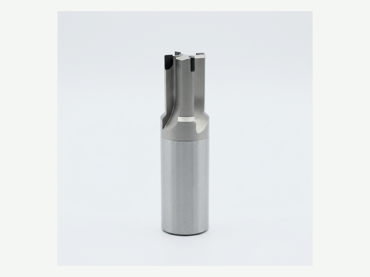
Send us the five readings before you change the reamer
A reamer that is returned for size usually comes back with a drawing and no machine data. With the five readings, a bore diameter and the tolerance band, we can often say which side of the interface is moving before a tool is reground.
Send runout at the edge, drift across a shift, holder and stickout, coolant at the tool inlet, and axis step and backlash, plus the pre-hole method and the material.
The custom cutting tool RFQ takes drawings and data together, and the tool itself is described on the custom PCD reamer page.
What published sources say about this
These are the pages we used for the machine-side points. Vendor statements describe the vendor's own product under the vendor's own conditions.
- Troubleshooting for reaming (reaming toolmaker technical library): names excessive tool or spindle runout among the main reaming problems, and advises changing one parameter at a time rather than several.
- Reaming and fine boring (toolmaker technical page): covers replaceable-head reamers and floating holders used on lathes to compensate axial misalignment between adapter and bore.
- Tool holders and tool clamping technology (tooling maker technical page): shrink-fit, hydraulic and collet chucks, with runout and balancing figures stated for the holder as a component.
- Toolholding (clamping equipment maker technical page): clamping devices and interfaces for rotating tools, including hydraulic expansion and shrink-fit families.
- Machine tool calibration (metrology equipment maker): geometry, thermal behaviour and on-machine verification of machine tools, which is where the drift check in this page comes from.
- Aluminum 6061-T6 property data (NIST): measured linear thermal expansion for a wrought aluminium alloy, the reference behind the drift-per-degree estimate in this page.
- Issues for measurement characterization (NIST/SEMATECH e-Handbook): bias and repeatability of a gauge reading, which is what a runout check is.
- Controlling bias and variability (NIST/SEMATECH e-Handbook): why the same reading must be taken the same way before it is compared across shifts.
- What is process capability? (NIST/SEMATECH e-Handbook): how a tolerance band and process spread are compared, the frame behind the five-point check.
- Chatter and vibration in machining (toolmaker technical library): vibration signatures and countermeasures behind the exit-band chatter mark described above.
- Bore roundness and lobing (toolmaker technical library): two-lobe and multi-lobe roundness errors and how they are read on a roundness chart.
Outbound references on this page are limited to pages we opened on 10 November 2026 (Asia/Shanghai). Figures quoted from holders are the maker's own figures for that product; they are not HENTRY measurements and were not taken on our machines.
Frequently asked questions
Can a PCD reamer run in an ER collet chuck?
It can, and for a short-run job with a wide band it often does. The limit is repeatability: a collet that has been in the cell for years may hold runout at the shank but not at the cutting edge, and it re-seats differently each time the tool comes out.
For production H7 work we ask for runout measured with the reamer clamped, and if it cannot be brought under about 5 um TIR, a hydraulic or shrink-fit holder is the cheaper fix than a reground tool.
How long should the machine warm up before a capability run?
Until the measurement says it has stabilised, not until a timer runs out. Measure a master ring or a first-off part every 15 minutes and start the trial when two consecutive readings agree within a fraction of the band.
On many machining centres that is 20 to 40 minutes; in a cold shop in winter it can be longer, and the fixture and the part need the same treatment as the spindle.
Is 5 um runout a rule we should put on a drawing?
No. It is a shop-floor starting point for finishing work. The number that matters is the share of the tolerance band the assembly consumes: on a 21 um H7 band, 5 um of runout is already a quarter of it before any other error.
Set the limit from the band and the allowance, and state where it is measured, with which tool clamped, at which plane.
Does coolant pressure matter for reaming or only for drilling?
It matters, but flow and aim matter more than the gauge number. A reamer needs the chip out of the hole, and in a blind aluminium bore the chip is the most common reason a good tool produces a bad wall.
Ask for pressure at the tool inlet rather than at the pump, confirm the passage is not restricted, and look at the flutes after a cut.
Updated 10 November 2026: added in-article figures; expanded and re-verified outbound sources; vendor names removed from visible copy. First published the same day. Scope: machine-side variables for PCD reaming on machining centres and turning centres. Reference limits are industry starting points, not HENTRY specifications, and no figure on this page is a HENTRY measurement.